


FIRST!
The Terrascout has been on ToysRUs shelves for many months now, serving as the most expensive Nerf product in the arsenal (license deals notwithstanding). In form and function, it is an R/C vehicle with both a video camera and a Rapidstrike mounted on top, all running off an 8S (~9.6V) NiMH rechargeable battery.
Modding the Terrascout is a bit different than modding your typical blaster. For one, there’s an entire PCB (printed circuit board) in the blaster turret that is designed for stock use. Trying anything silly could, for the average Nerfer, result in a camera that doesn’t work. Or you might make things work, just not as well as you’d hope. If you have patience and keep your circuits separate, however, you can get an R/C vehicle that’s downright SCARY. (See video at the end)
WARNING: THIS IS A LONG POST!
The Guts of the Blaster
First, a few critical parts that are nice to look at, but that you won’t be messing with today. The motor at the bottom of the turret controls the elevation of the blaster unit. There are also two limit switches, one in each direction of movement.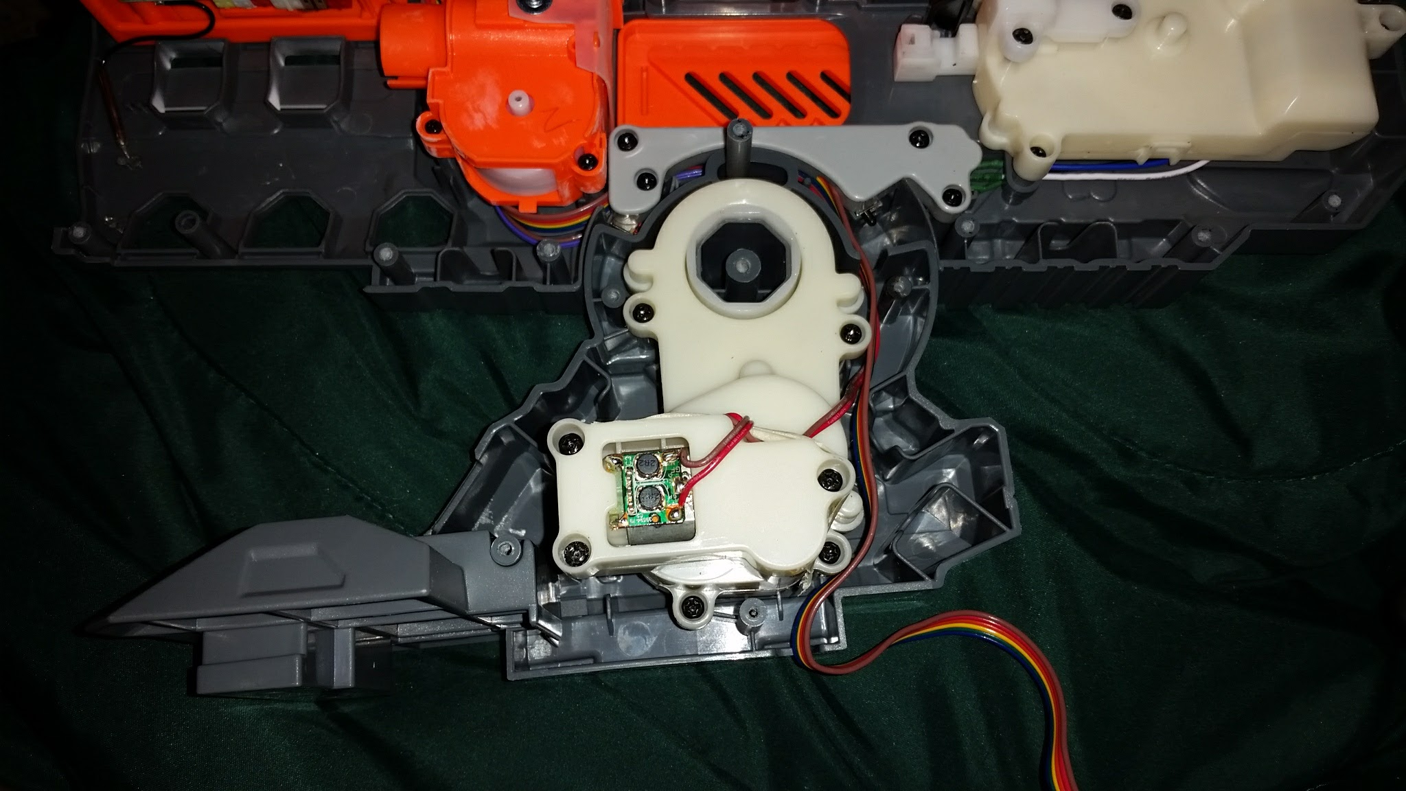
Next is a simple look at the dart pusher. Your motor drives a worm gear, which after going through several more gears drives a reciprocating piece of plastic. Hello, Rapidstrike part!
Two safety switches hide under the pusher assembly. The top one depresses when a magazine is inserted. The bottom one is meant to stay open, but breaks the circuit when the jam door is opened.
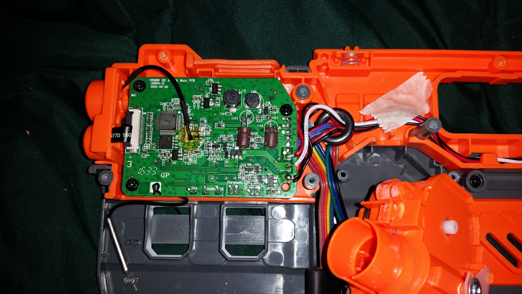
Most switches and motors in the turret have clip-in connectors mounted along the lower portion of the PCB. The rainbow (the colorful wire bundle that connects to the base of the Terrascout) is soldered directly to the board, as are the safety switches for the jam door and magazine. The safety switches can be easily bypassed if you so desire.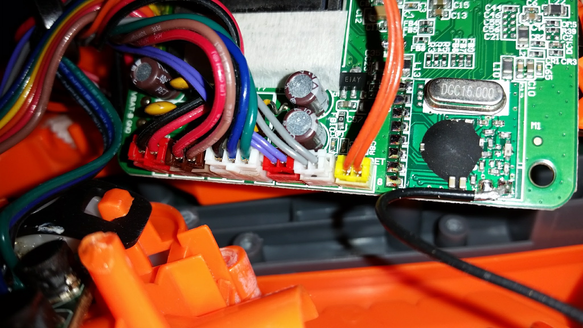
The flywheel motors naturally have their own PCB. These motors don’t actually draw a lot of current; only a couple of amps at most. When stock, the flywheel motors consistently spit darts out at 68 fps. BUT WE WANT MORE!
Parts List
The following sections assume that you have a good grasp of basic modding skills, electrical knowledge, and common sense. If you are lacking in any of those, DO NOT ATTEMPT THIS AT HOME. Practice makes perfect, and there’s no need for your first project to consist of a potentially ruined $200+ toy. Try a few Stryfes or other (cheaper) projects first.
There will be several required tools and materials, many of which I have neglected to write down. I will editing the list to completion after this post is online. Be sure to pre-solder all connection points, and be sure to have heat shrink tubing in place to cover the bare wire when ready (in some cases, you may need to test connections with a multimeter before covering them in heat shrink).
Tools
Soldering Iron
Wire cutters
Wire strippers
Power Drill
Rotary tool
Needle-nose pliers
Heat gun
Digital Multimeter
Small diameter screwdrivers
Materials
Electrical Solder w/Rosin Core
Heat shrink tubing, various sizes
Mounting tape
At least 16awg stranded wire for high power circuits
18-22awg wire for low-power circuits and signals
Bright White LED
CdS Photoresistor
Resistor (at least 2000 ohm)
Rectifier Diode IN5400 series (I used an IN5402)
N-channel MOSFET (IRLB3034PBF is recommended)
DC-DC Buck Converter
Replacement Flywheel Motors
Project box from your nearest elecronics/hobby store
Handy dandy box of electrical connectors
Basic Circuit Overview
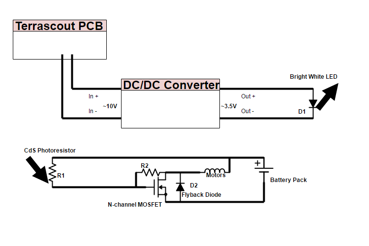
We plan on replacing the stock motors with ones that will require a lot more current than the current system can provide. Since we don’t want to fry any existing electronics, we will therefore convert the existing flywheel circuit into a signal. The operating voltage of the LED is 3.3V to 3.6V, while the average voltage in the flywheel loop is 10.1V on a freshly charged battery. Therefore, we will need a DC-DC Buck Converter to drop the voltage down to the appropriate level. Technically, you could also use the right-sized resistor, but this way you can adjust the step-down precisely and not bleed off power as heat.
Note that you could do something similar with the pusher motor. I chose not to because I simply didn’t feel like emptying my clips so quickly.
Making the Signal Circuit
The three wires of the original flywheel circuit. From an early build with a shortage of parts, thus the bundle of resistors.
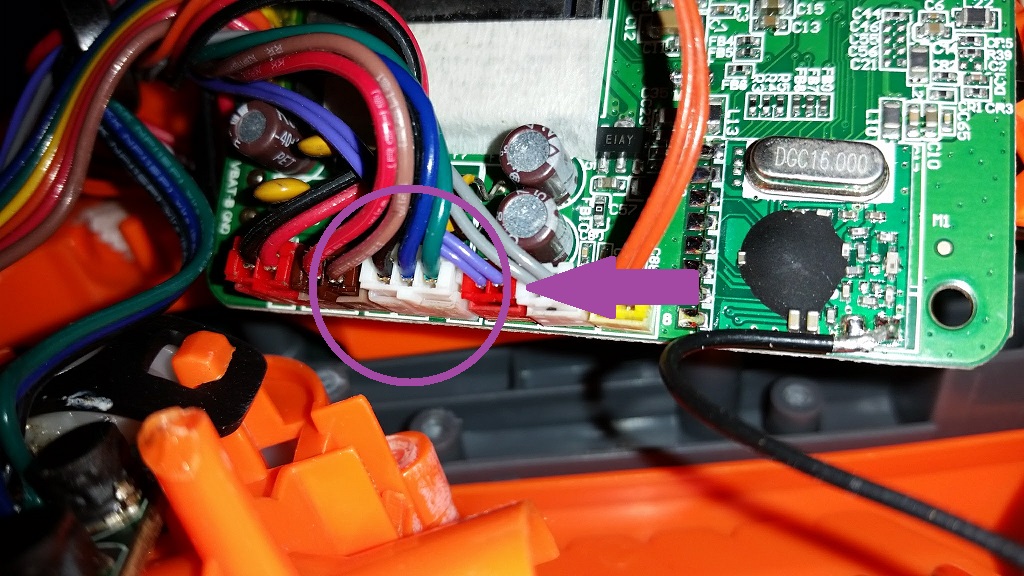
The circuit in question consists of two positive wires (blue and green) and one common wire (black). It hooks into the main PCB via a white plug and connects at the other end to the stock flywheel motors.
Cut the wires right at the flywheel motor PCB, and thread the trio outside the shell. Strip the ends of the wires, and solder the blue and green together. You could technically only use one, but I prefer doing this so as to not have any forgotten and potentially loose wires hanging around.
Now for the buck converter. This Wikipedia article does a decent job explaining the basics for the device. For those who want an oversimplified analogy, think of it as the water tower supplying your town.
If that analogy fails, just think of the buck converter as your circuit’s recoil buffer. You don’t want the whole voltage directed into your signal, do you?
Enough Analogies, What Now?
In my case, I chose to solder wires into the + and – holes on both the input and output sides, instead of directly tying the existing wires into it. Reason? So I can hook the multimeter in and make adjustments. On the buck converter’s board is a small rheostat used for adjusting the target voltage. After you solder the connections on the input side, you’ll need a Philips screwdriver to turn the rheostat. Hook up the multimeter, then use your Terrascout remote to fire. Measure the output voltage and adjust until you arrive within the operating voltage of your chosen LED. Once that is set, you can mount it to the turret with simple mounting tape.
Once you’ve done all this, solder small diameter wire to the leads of both your LED and your CdS photoresistor (the slightly longer lead on the LED connects to the + end). Seal off each lead with heat shrink, and then set the two elements to face each other. Next, find a larger diameter piece of heat shrink and cover them both so as to make them “one unit”. This way, nothing but the LED will activate the photoresistor. After all this, solder the LED side to the signal circuit and mount where desired.
Motor Installation
It turns out there is more space in the Terrascout shell than expected. There are two tubular spacers sitting under the motor cage. If you use 130-sized motors as replacements, these are of no consequence to you. If, however, you elect to install 180-sized motors, then the removal of these spacer will be enough to allow installation without holes in the outside of the shell.
Well, normally.

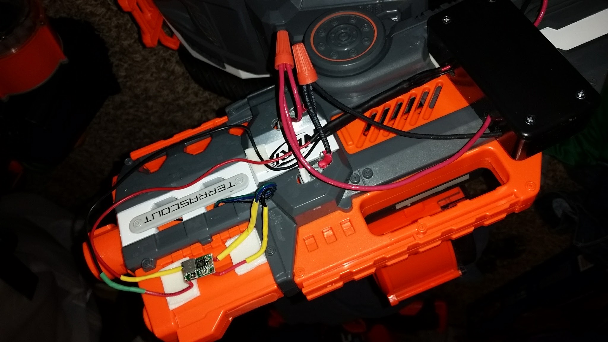
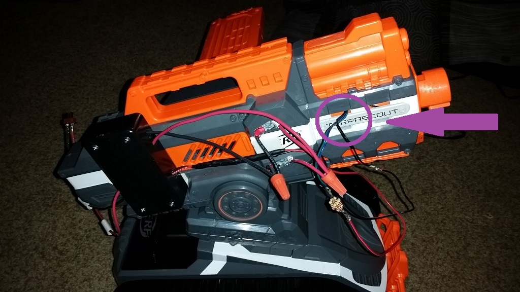
Ideally, you should be able to run most of your wires close to the body of the turret, if not mostly within the turret itself. Most of my wires now sit next to the blaster. Once I get a small cover printed, I’ll redo the motor connections and make things far more aesthetic.
How to Use a MOSFET
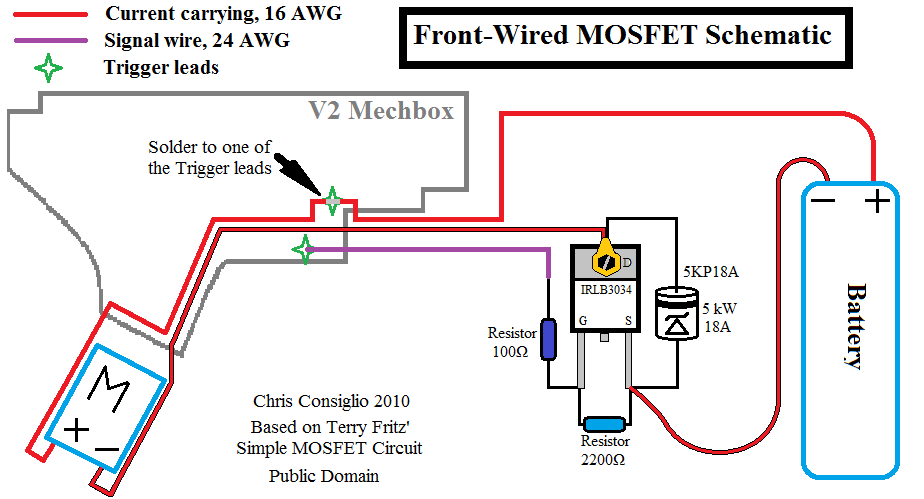
If an electrical circuit was a fluid circuit, a properly done N-channel MOSFET would be a large but delicate normally-closed valve with a pilot (the gate terminal, or “G”). A signal to the gate terminal of sufficient pressure will open the valve. If you cut off the signal, it closes. However, if your circuit contains elements that handle energy in a certain way, shutting the gate can result in a sudden surge of pressure in reverse that can damage the valve, if not the rest of the circuit. Therefore, you need a mechanism to bleed off or reduce the pressure (in plumbing, this pressure surge is called “water hammer”). The diode does this job. In its reverse orientation, it does absolutely nothing in normal circuit operation. In cases of switching off the valve, it acts as a check valve to equalize the reverse pressure, and prevents damage.
Motors, inductors, and various elements don’t produce a reverse “resistance”, they generate a voltage within themselves because of the magnetic fields involved. When the circuit is cut and the fields collapse, a brief but large voltage can be generated going in the opposite direction. Not handling it can fry your MOSFET, and we prefer not having burning electronics. ALWAYS USE A DIODE.
Back to the Blaster Mod…
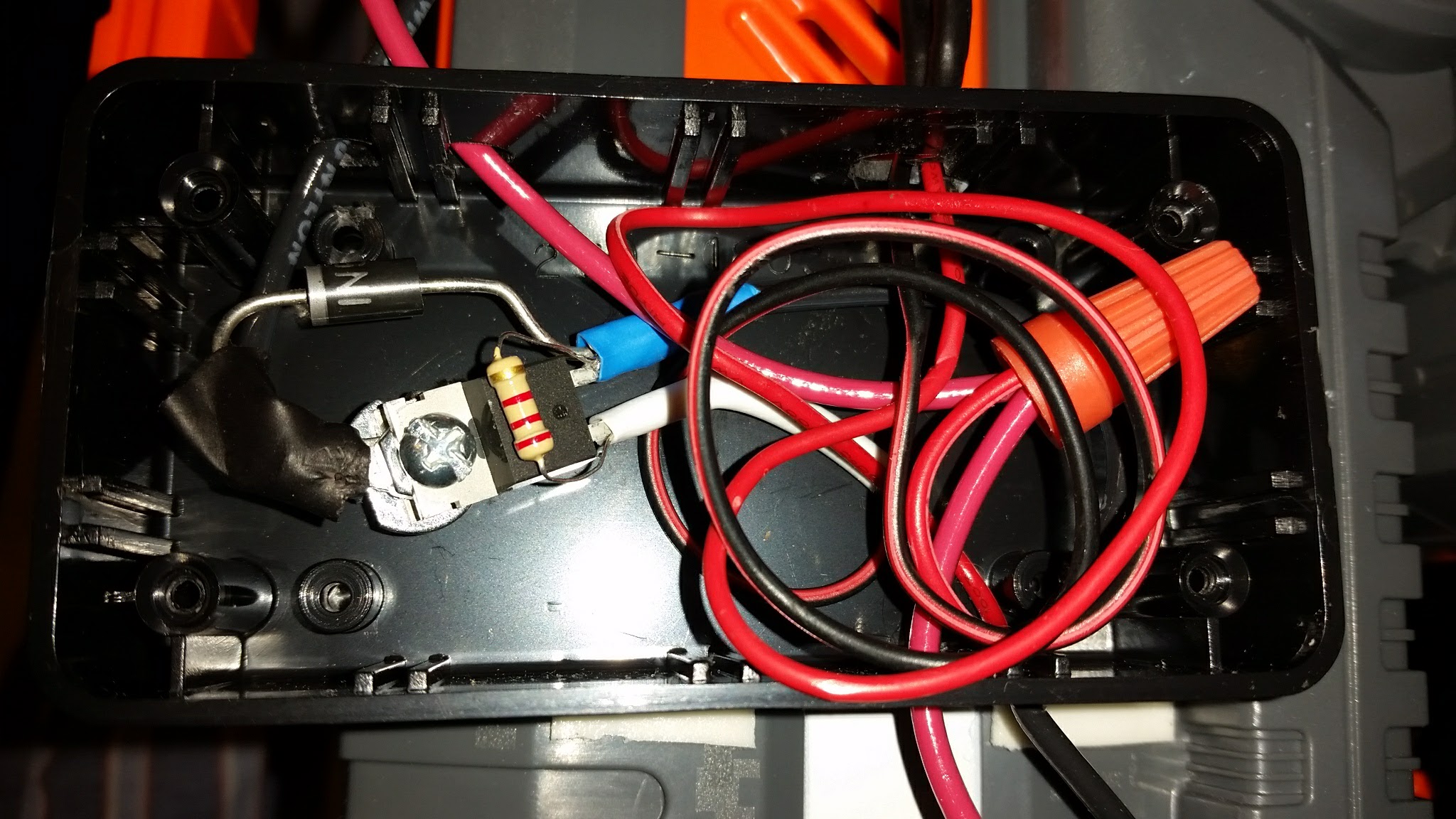
Solder the other main current carrying wire to the source lead, and one of the signal wires from the CdS photoresistor to the gate. Heat shrink where appropriate. Now wire the signal and positive motor leads with the positive battery lead, etc., and make a complete circuit. I drilled holes in the other side of the project box and mounted the 3S Lipo on the magazine well.
THE END OF THE ARTICLE. THANK THE FOAMY GODS.
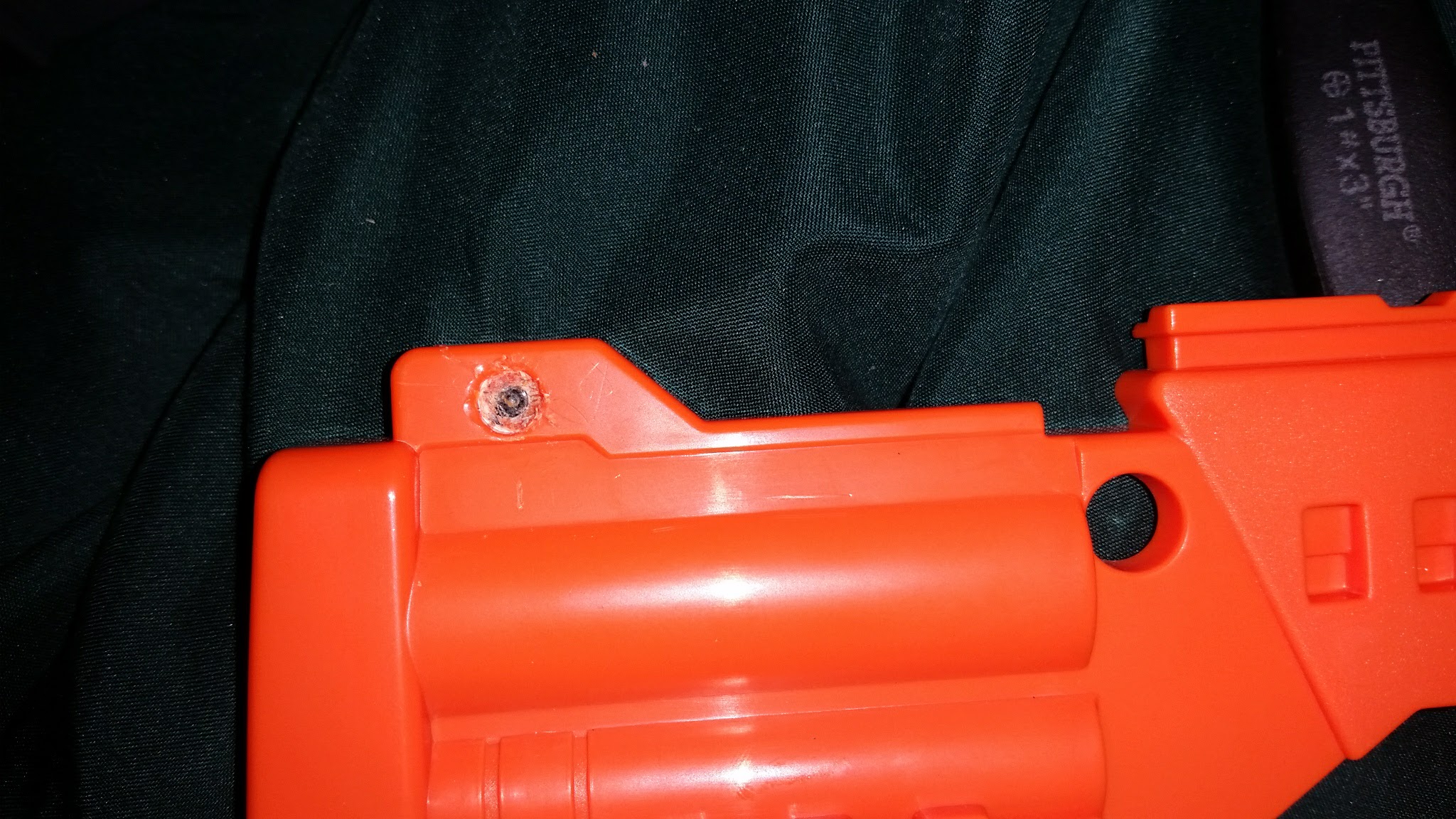
Under the initial build, there was one other problem I had: I ACCIDENTALLY PULLED THE R/C ANTENNA CLEAN OFF THE MAIN PCB. That’s a big no-no. While I did make a hasty repair job, it resulted in a unit that would function for a few minutes before losing the connection to my remote, at which point I would have to do a hard reset, turn everything back on, and go again. This was fixed once I got home.
In the meantime, I at least got a few minutes of footage chasing after people at a Nerf war! Big thanks to Naptown Nerf for hosting what turned out to be an amazing war with 60+ people in attendance. I’m sure me learning to drive the Terrascout didn’t help the antenna issues any. Look at that pretty wall! SPLAT!


In the end, I achieved consistent 100 fps dart speeds out of the Terrascout using a partially drained battery and a less than idea setup. After tinkering a bit more, I expect to get at least 110 fps, if not lightly more.
Thanks for checking this out, and to those wishing to try this, good luck!