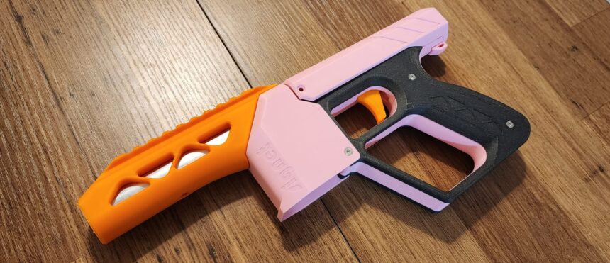
Acorn Armaments Signet Build/Assembly Guide
December 18, 2025It’s a bit early for the review – I’ve only just finished printing the files after ordering the hardware kit from Out of Darts a while back – but I felt there needed to be a post. There doesn’t seem to be a build guide online yet! And while someone like me can figure out the assembly after staring at the pieces long enough, even I came across a few small difficulties during the process. To that end, let’s make a post with pictures!
I’ll hopefully have time to use this blaster over the weekend. But since I’ve seen the creator (and others) use this blaster at Humans v Zombies games throughout the year, I’m sure it’ll hold up just fine!
1) Print Your Parts
This shouldn’t have to be said, but it’s a 3D printed blaster, and you need the parts to make it! There is a basic guide with instructions for print orientation on the Printables page, which should prove helpful for the oddly shaped pieces and the bits that need specific supports.
I won’t tell you what to do; I’m not your mother. But reading the basic guide seems like a good idea.
Additionally, if you prefer having a mag release lever, a remix of a few parts exists thanks to Gargunkle. You’ll need an extra spring if you go that route, and adjust this build guide accordingly.
2) Assembly Prep
Here’s where we get picture heavy! I’ll do my best to format things, since a website is a bit different from making a PDF. Besides, I’m assuming that at some point, either the creator makes a PDF, or Out of Darts makes Dr. Flux or one of the other employees record a video build guide. Until then, you’re stuck with me!
Tools needed:
- 2mm Hex key/Allen wrench
- Soldering iron (or a heat gun with a tip for heat set inserts). Presses for heat set inserts exist or can be made, but I’m assuming you’re not doing these on an industrial scale.
- (optional depending on tolerances) Hammer and vise grips. The plunger requires a pin insertion, and if your prints are tight, you might be inserting a pin partway, then using another pin as a punch to finish the process. Honestly, I just held the plunger head between my feet and aimed carefully, but there are MUCH better ways. Consider gripping a pin with needle-nose pliers, heating it up with the soldering iron, then inserting quickly while warm. Just be sure everything is lined up when you do so. Otherwise you’ll be printing plunger parts again.
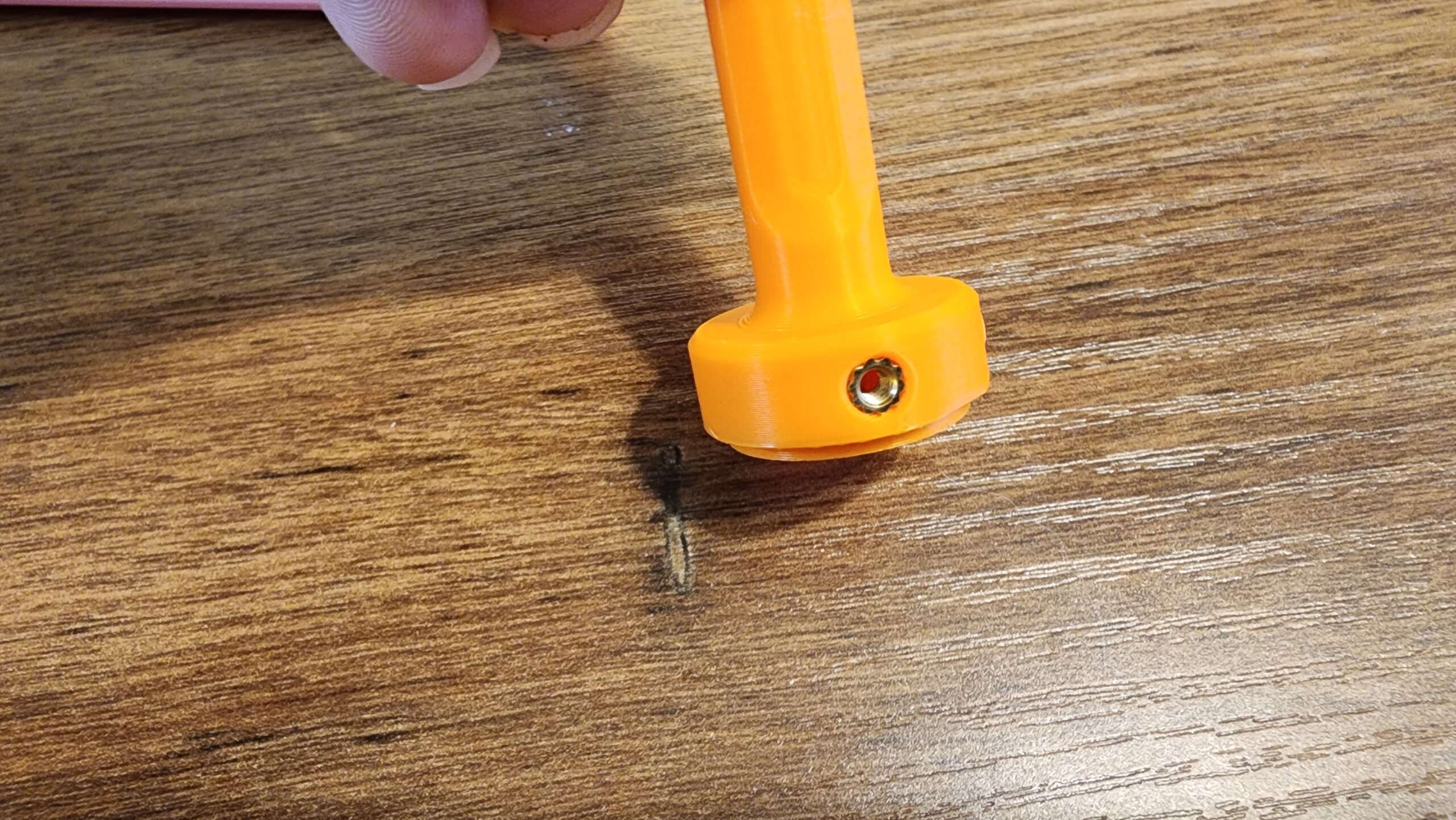
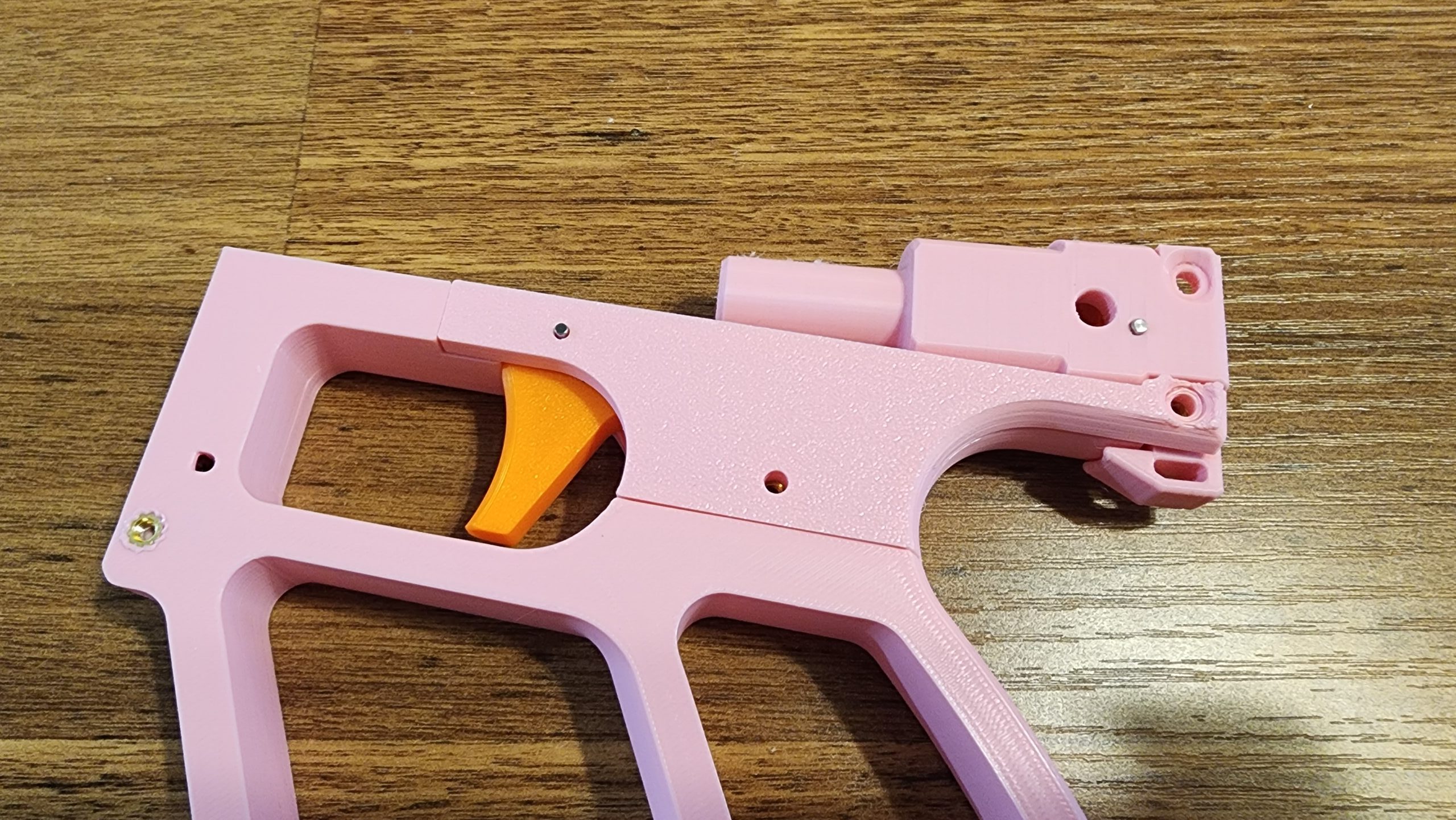
3) DETENTS!
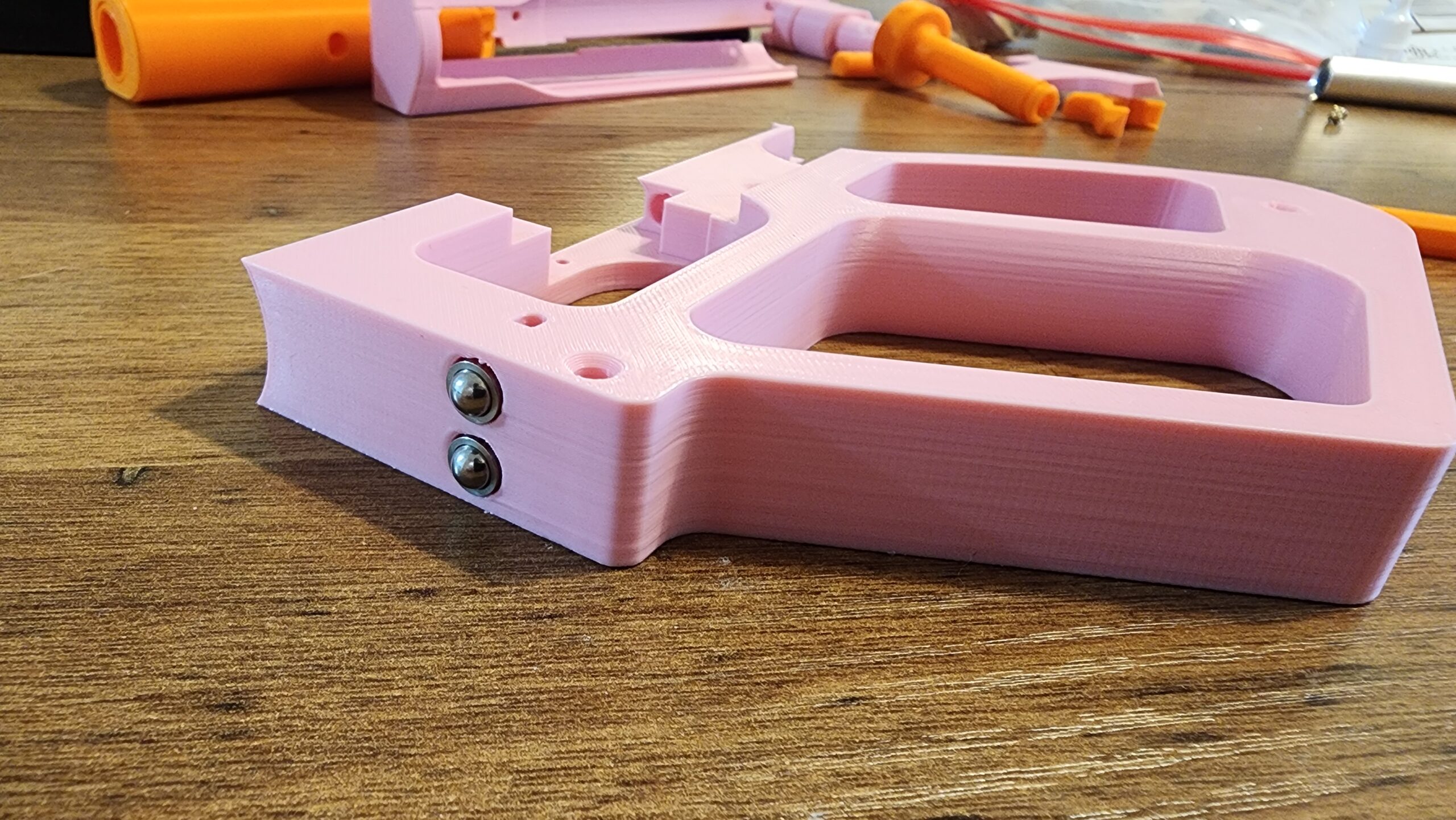 This one is simple! We’re just using these inserts in place of a magazine release. When you pull the magazine, the ball bearing detents are pushed inward. It’s advisable to use some kind of adhesive to bond the detents in place.
I’m listing this step here for a simple reason: if you can’t easily insert your detents, then you need to reprint the frame. My first frame pulled up partly from the print bed, so the holes for the detents were oblong instead of round.
It’s at least a good visual reminder before you do more. If you’re experienced in 3D printing, you can just look at a piece and realize something went wrong. For those less experienced, that’s why I put this step here!
Even so, check the rest of your prints. Regardless of how much you think you know, double check everything.
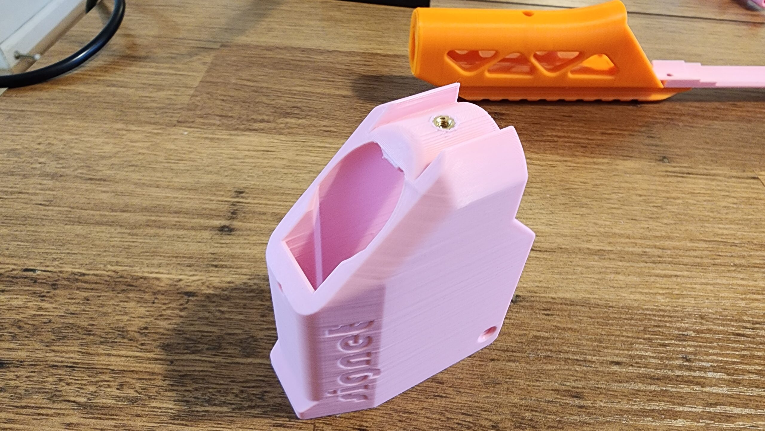
4) ALL THE INSERTS
 There are 13 heat set inserts to be placed in various places. I’ve done inserts before, using larger M5 screws, which were easy. The Signet, however, uses M3 screws and inserts. The smaller diameter has less room for error, as it turns out.
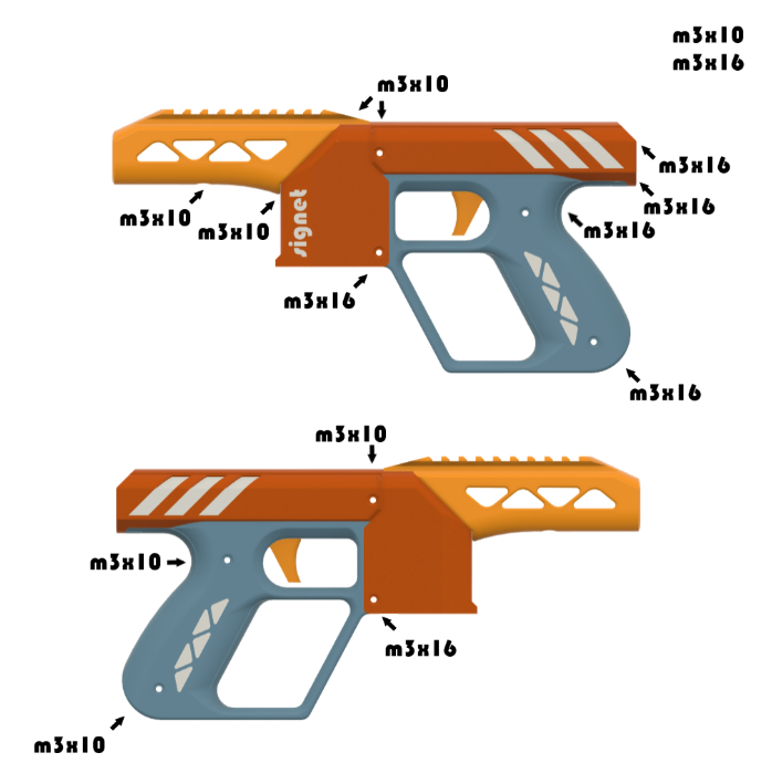
I’ve included a picture from the basic print guide – while it shows what screws go where in the blaster, it also (inherently) shows where the heat inserts should go. This is what I ended up looking at to make sure I was thinking correctly, and it helped a lot. Use it at the end to reference where each screw goes.
For handling the heat set inserts: take your 3D-printed piece, and place the insert in the corresponding hole. The smooth end should face down, while an outside ring of angled ridges should be on top. Heat your chosen tool (soldering iron, etc.) and place the tip inside the heat set insert, pointing straight down and *lightly* pressing it down vertically until flush.
This is the hardest part of assembly due to the small diameter hardware being used. If you press down with too much force, the melted plastic will fold over on itself under the insert and obstruct later screw insertion. Trying to solve THAT later becomes a pain in the ass, because you’ll likely strip screws or damage your hex key/driver bit thanks to the obstruction.
Two inserts go into the pusher, one on each side (the second isn’t pictured).


Three of the M3-16mm screws are essential – the two going through the catch block, and the one that goes through the grip scale, trigger cover, and frame. The other ones can be replaced with M3-10mm screws if you get too much resistance.
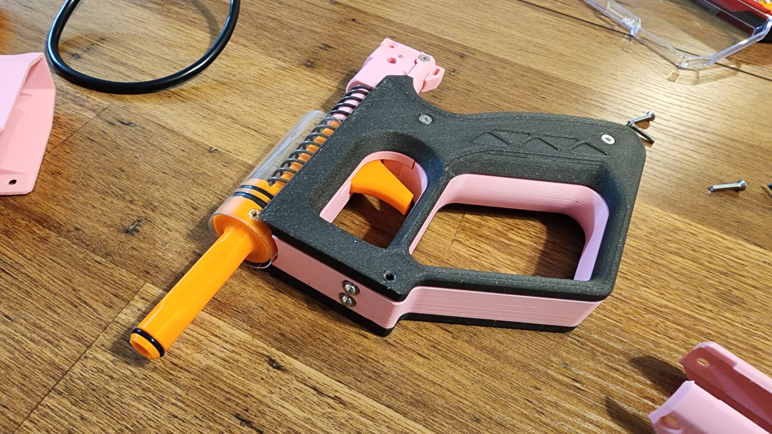
5) Prep the Plunger Tube
Once you get past the difficulties of putting a pin through the plunger head and plunger rod (see above), the rest is easy. Mount your o-rings onto the pusher and the plunger. There is an extra o-ring that serves as both seal and cushion at the front of the plunger tube.

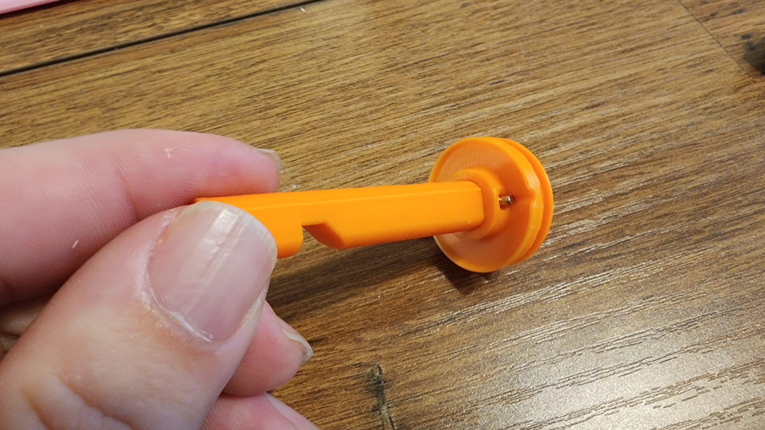

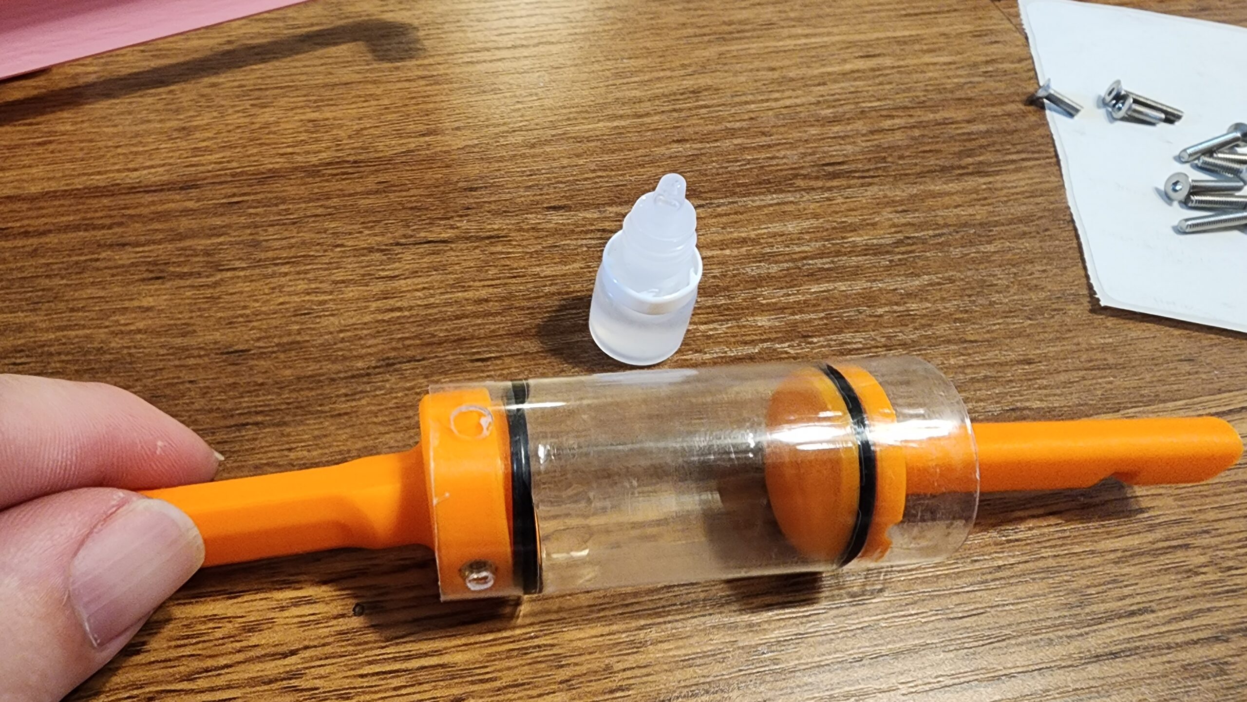
The pusher will line up with the pre-drilled holes – two with the inserts, and one hole with a knob on the side of the pusher. Apply your lubricant liberally.
6) Screwing Things Together
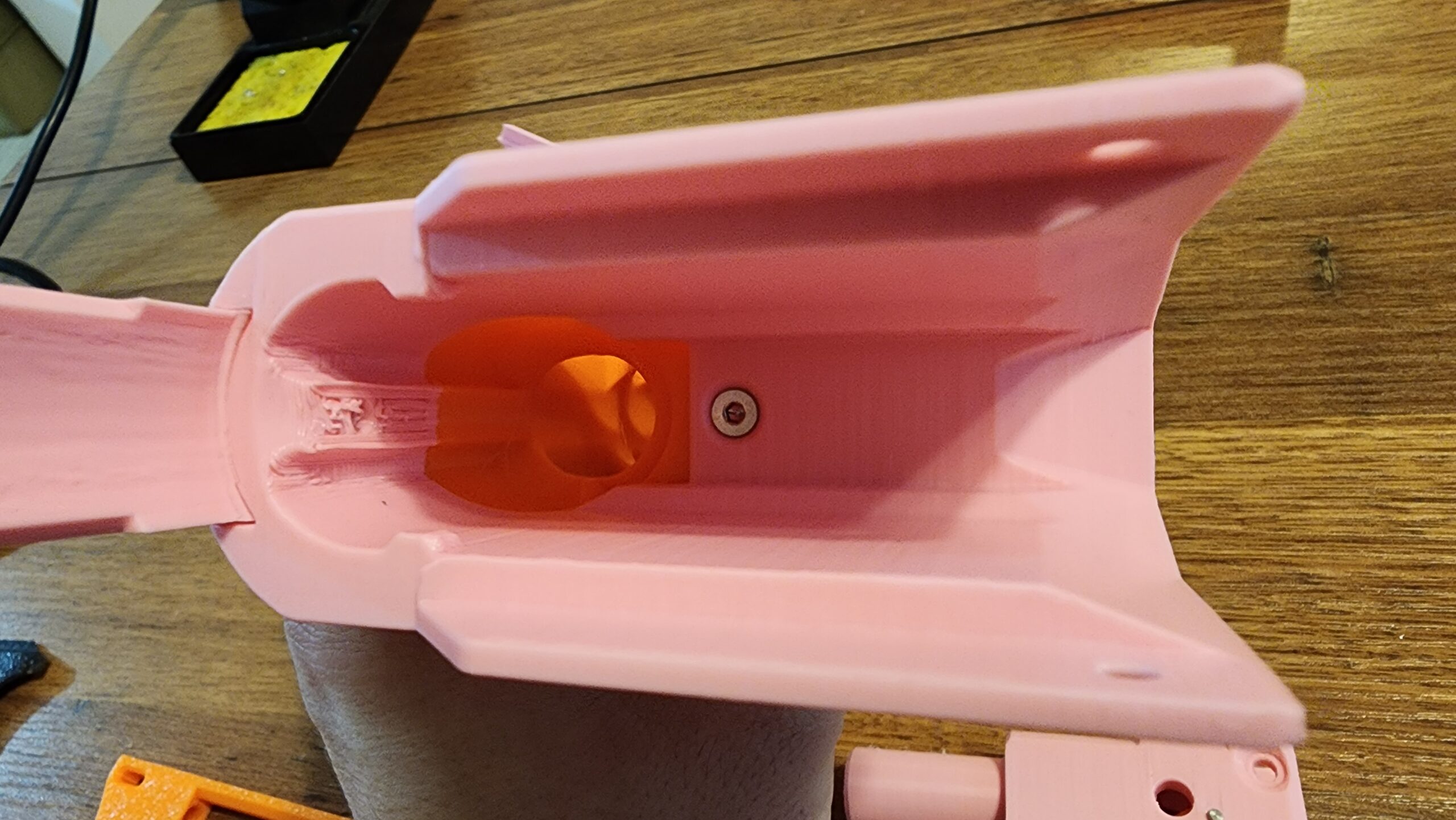
Now we start to see things come together! Start with the front of the blaster. Insert the top strap into the muzzle (remove any extra print artifacts as needed). Insert two of your M3-10mm screws: one from the mag well into the muzzle, and another coming down through the muzzle, top strap, and mag well. Also, have a cute picture of Joey sleeping near me because it’s a rainy day and she just want to be near me!


Set that piece aside.
Take the catch block and insert your catch spring. There’s only one space for it. Then, insert the sear into the catch block, coming up from the bottom. You’ll need to push it up into place at an angle, where everything line up perfectly. Once that’s done, use a screwdriver or other thin tool to make sure the catch spring is fully contained – you’ll likely have a coil or two out of place. Finally, line up the holes in the catch block and sear, and insert a pin (heat lightly to make the process easier).


7) Another Section Because It Makes The Readability Score on WordPress Stay Green Instead of Red
The catch block assembly latches onto the back of the frame. It’s a tight fit, requiring you to press the pieces together while rotating. Doing this puts the arm of the sear within a round channel. You’ll know it when you see it.

After you’ve snapped that in place, you can insert the trigger, pressing up against the sear. There is space for another spring under the trigger, if you have one on hand, but it’s not necessary. Put in the guide pin for the trigger, then add the trigger cover. At this point, you can put in an M3-16mm screw into the bottom rear cavity of the catch block.
 At this point, you can screw on the grip scales, one on each side of the blaster. Note that you should, for now, only do the holes at the bottom of the grip and behind the trigger.
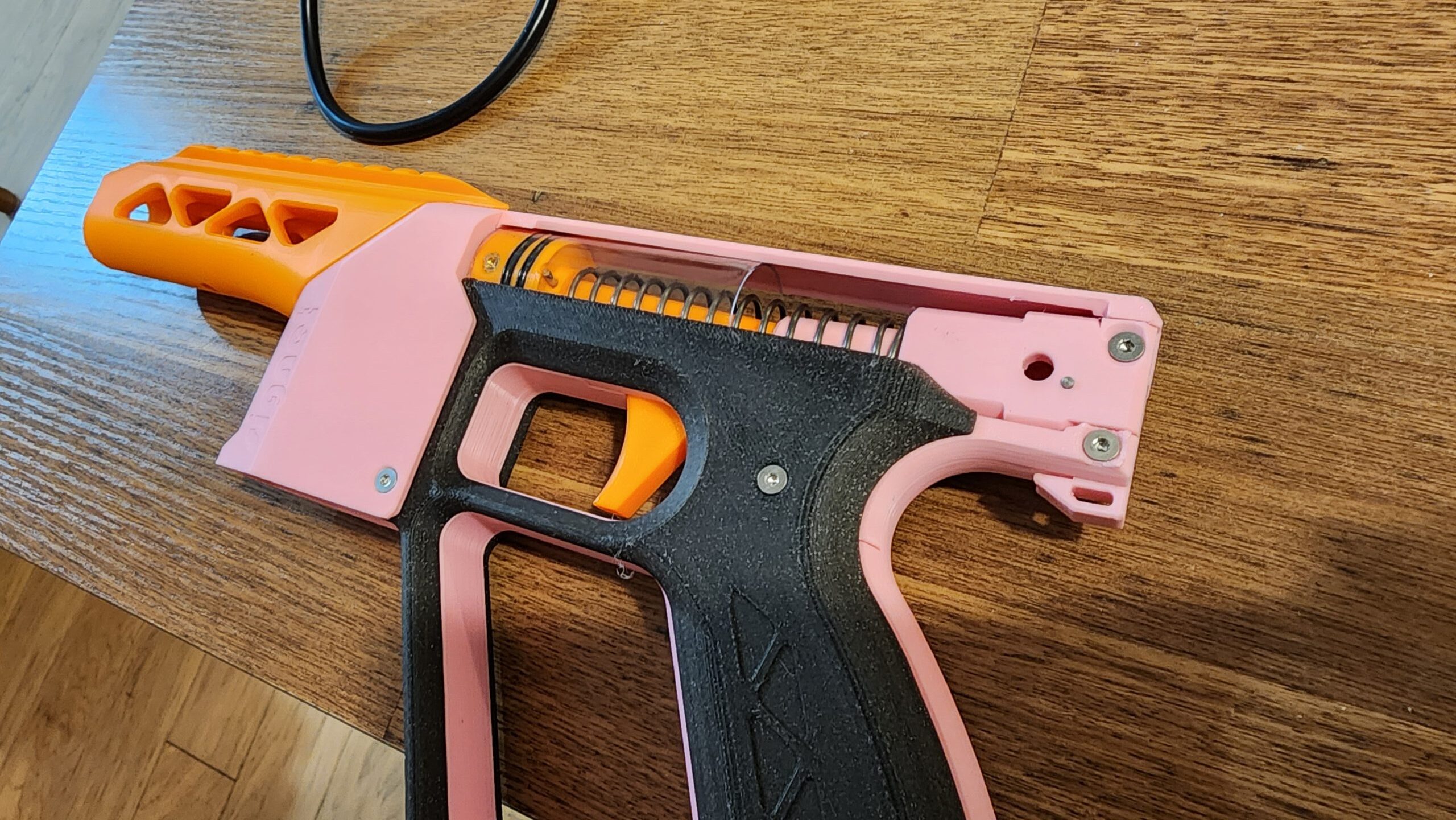
After those screws are in place, put the plunger and associated parts in place. Make sure that the main spring is in place, and that the catch slot on the plunger rod is facing down. Otherwise, you’ll just have to take things apart again and flip it over.
If everything looks good, move on to the next step!
8) Final Touches
Line up the front and back of the blaster, and insert the two screws that connect the mag well to the grip. Also insert the M3-16mm screw that connects the top scale to the catch block. You’re almost there!
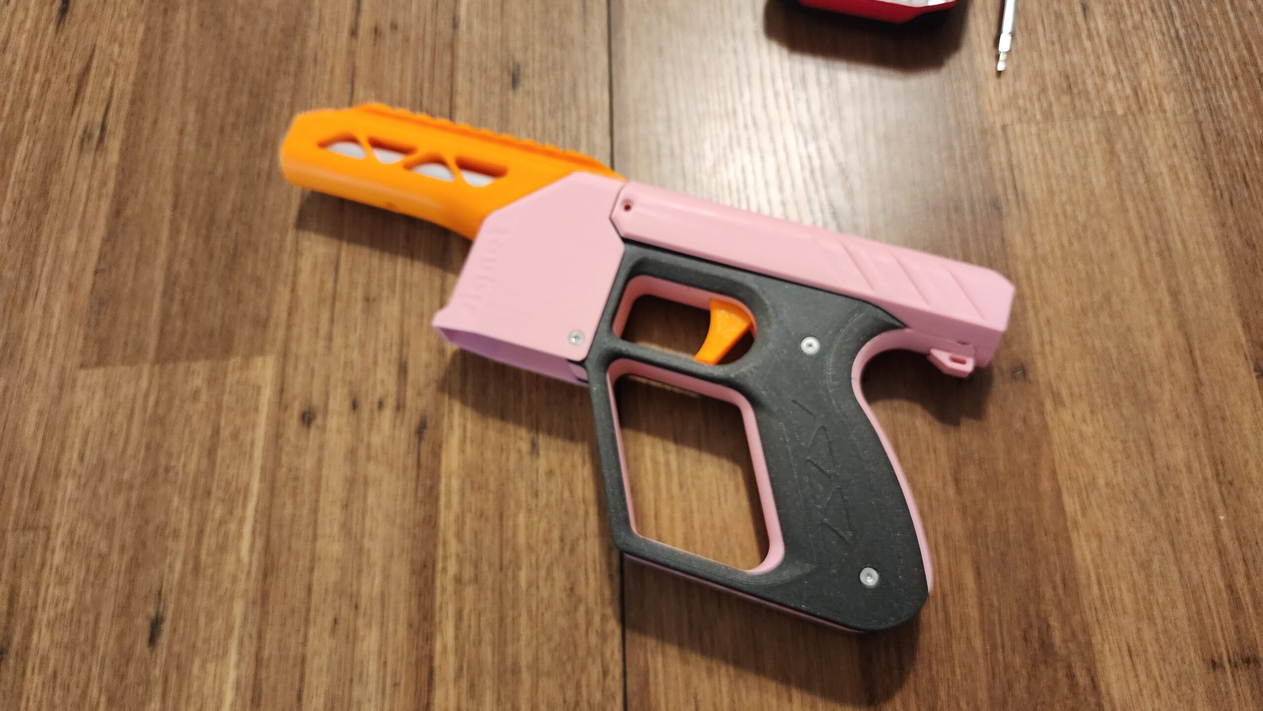
The last thing to add is the priming slide (plain, or T-pull, depending on the file you chose to print). Remove any printing artifacts, and slide it in place from the rear of the blaster, flexing a little bit as necessary. The piece should snap into place around the tops of the grip scales and the plunger tube. Insert two M3-10mm screws through the slide into the pusher (yep, the pusher, plunger tube, and slide all move as one piece).
Finally, insert the barrel from the front of the blaster, and use the last M3-10mm screw as a set screw in the bottom of the muzzle, securing the barrel in place. The barrel should be slightly recessed, and the pusher should sit inside it when the breech is closed.
Warning: count(): Parameter must be an array or an object that implements Countable in /home/hju78utsnbn3/public_html/wp-content/themes/blaster-hub/functions/ps-content/post-content.php on line 206