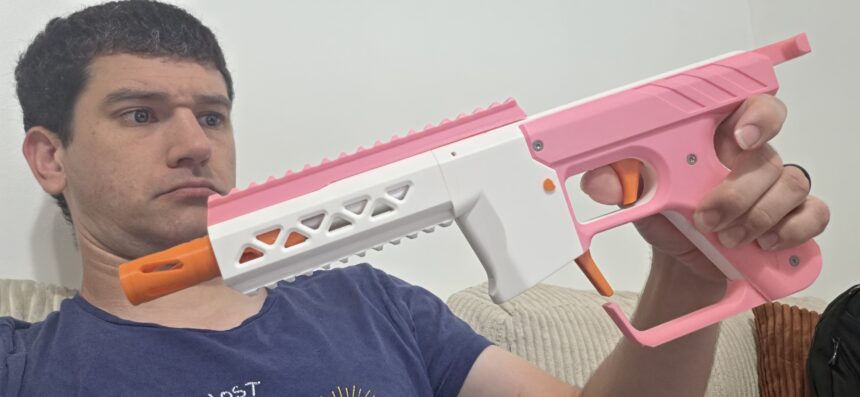
Acorn Armaments Signet V3 – Assembly Guide Pictures!
September 21, 2026Editor’s note: I got a hardware kit for the Signet V3 from Out of Darts (coming soon!). Thanks for sending this out! Also check the Printables page!
We’re not to the review stage *yet*, but between the fact that the blaster is incoming, and that there isn’t an assembly guide yet, I figured I’d take some pictures for documentation. I did this for the original Signet, even if I failed to actually post a review (I enjoyed the first version, to be clear).
This time around, the design has been refined, and I’ve had a chance to use the blaster in-game after printing and tweaking parts. So let’s get the pictures out of the way before a review!
Tools Needed!
I’ll assume you know how to use screwdrivers and other tools. If you don’t…this probably isn’t the place for learning.
In particular, you should have, at minimum, an M2 hex key/driver available for tightening the included screws. Small pliers will also be handy for grabbing and pushing the dowel pins into place. Have a plastic and o-ring safe lubricant handy (some comes with the hardware kit).
If, by chance, your plunger tube is too long, scissors are adequate for carefully cutting a strip off the tube to get it to size.
Part 1: Get a Grip
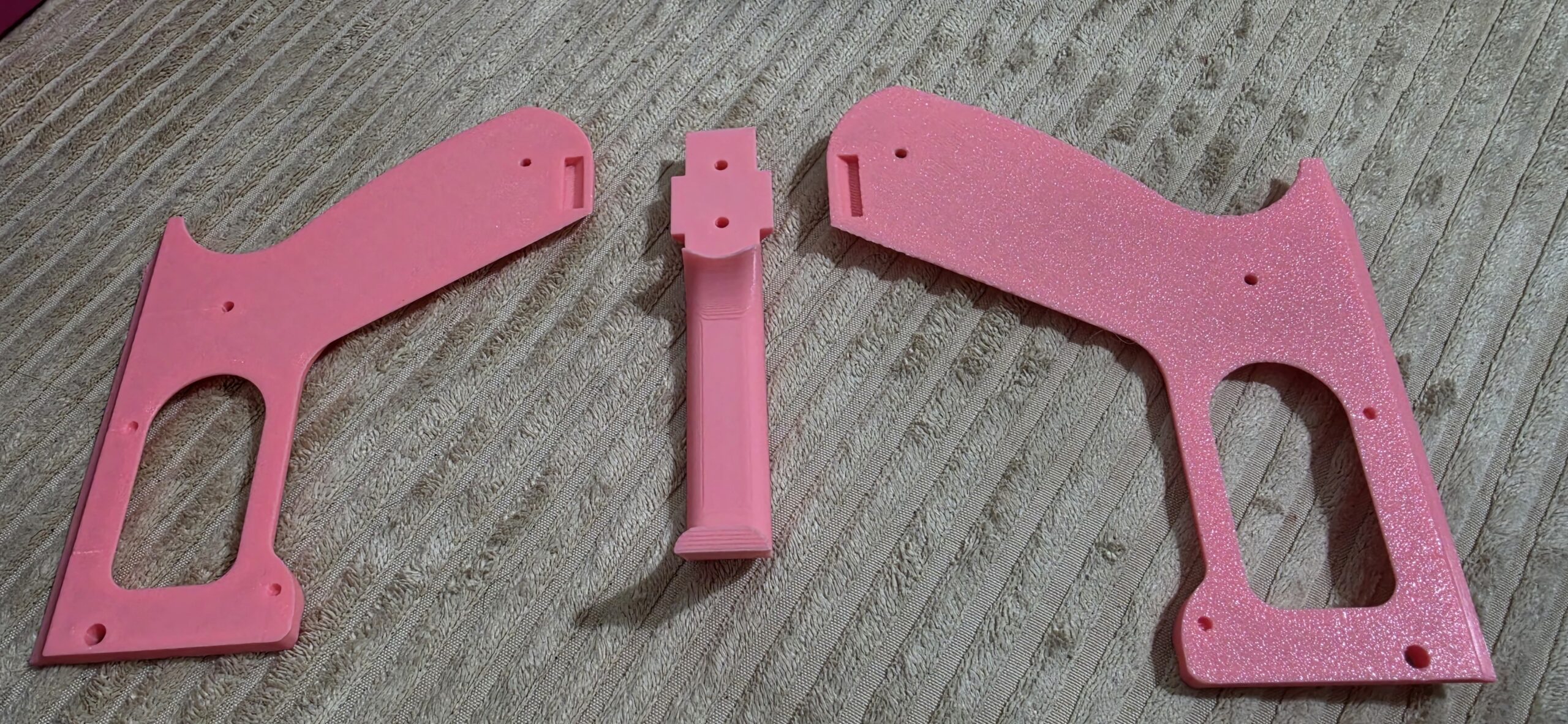
So you printed the grip frame! You should also have printed two standoffs. Those have slots in them for M3 nuts to slide in. Slide in the nuts, then push the standoffs into the frame. There are three more nut slots at the base of the frame – one for the grip base, and two for the stock attachment point, if you printed one. The stock is optional, so I’ll skip that step and just do the single nut for the frame base.
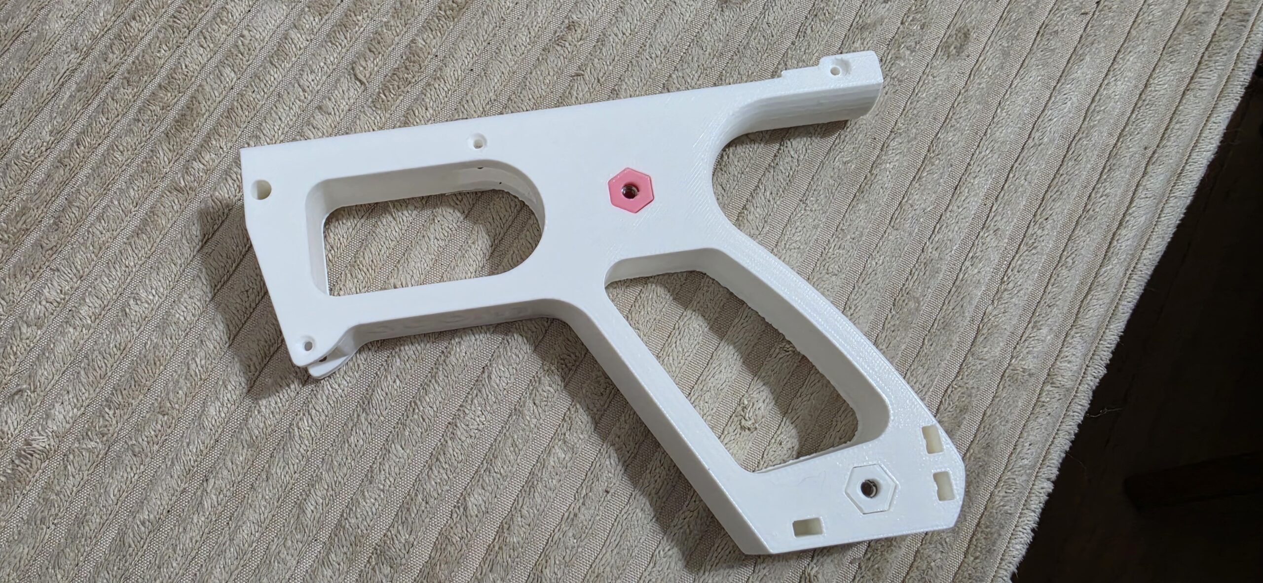
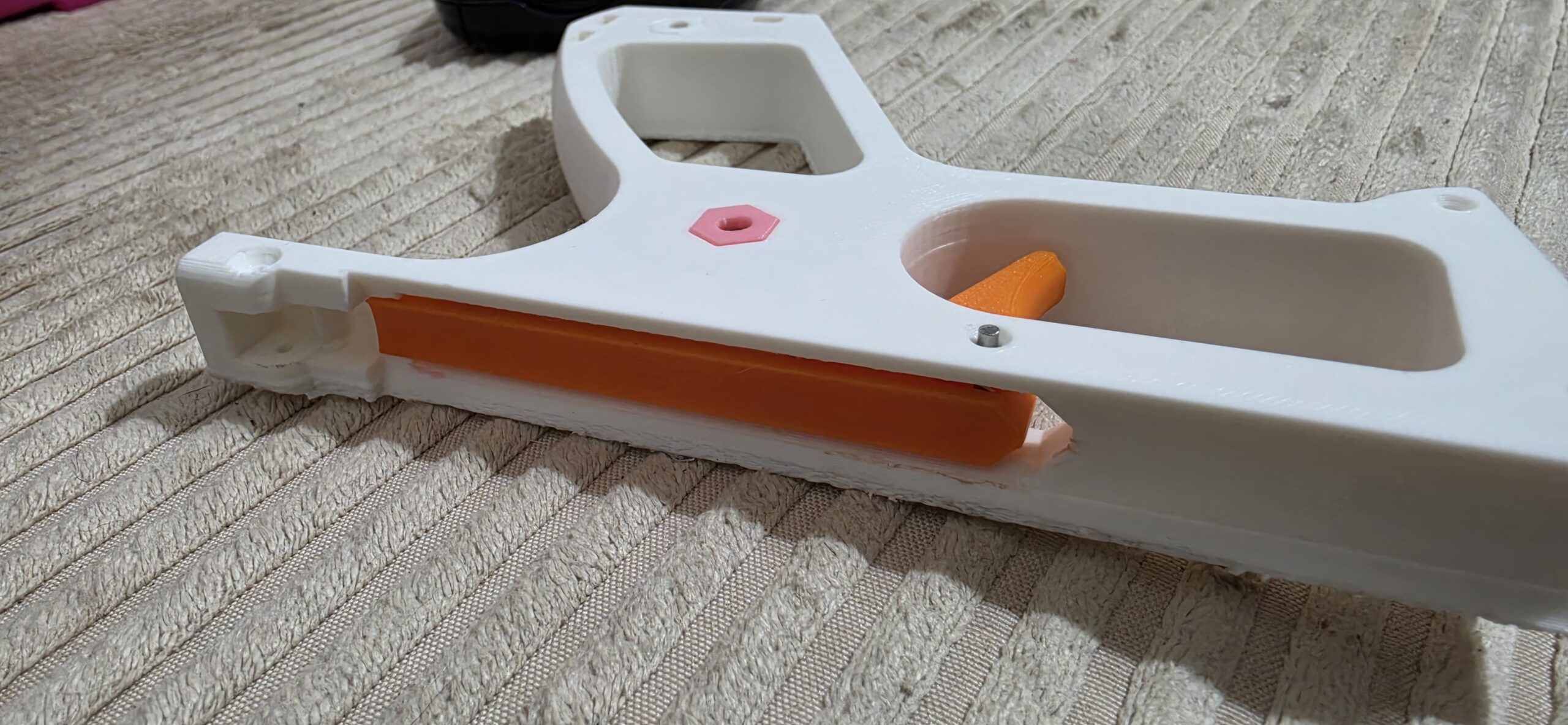
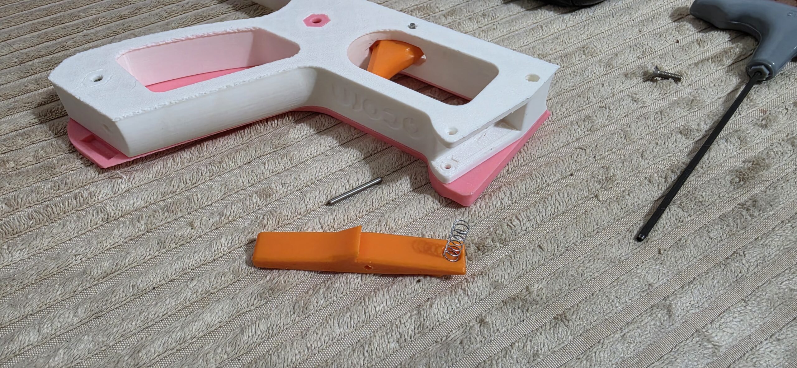
The trigger slides into the grip frame, and is held in by a 2mm dowel pin. Lube this area a bit upon installation.
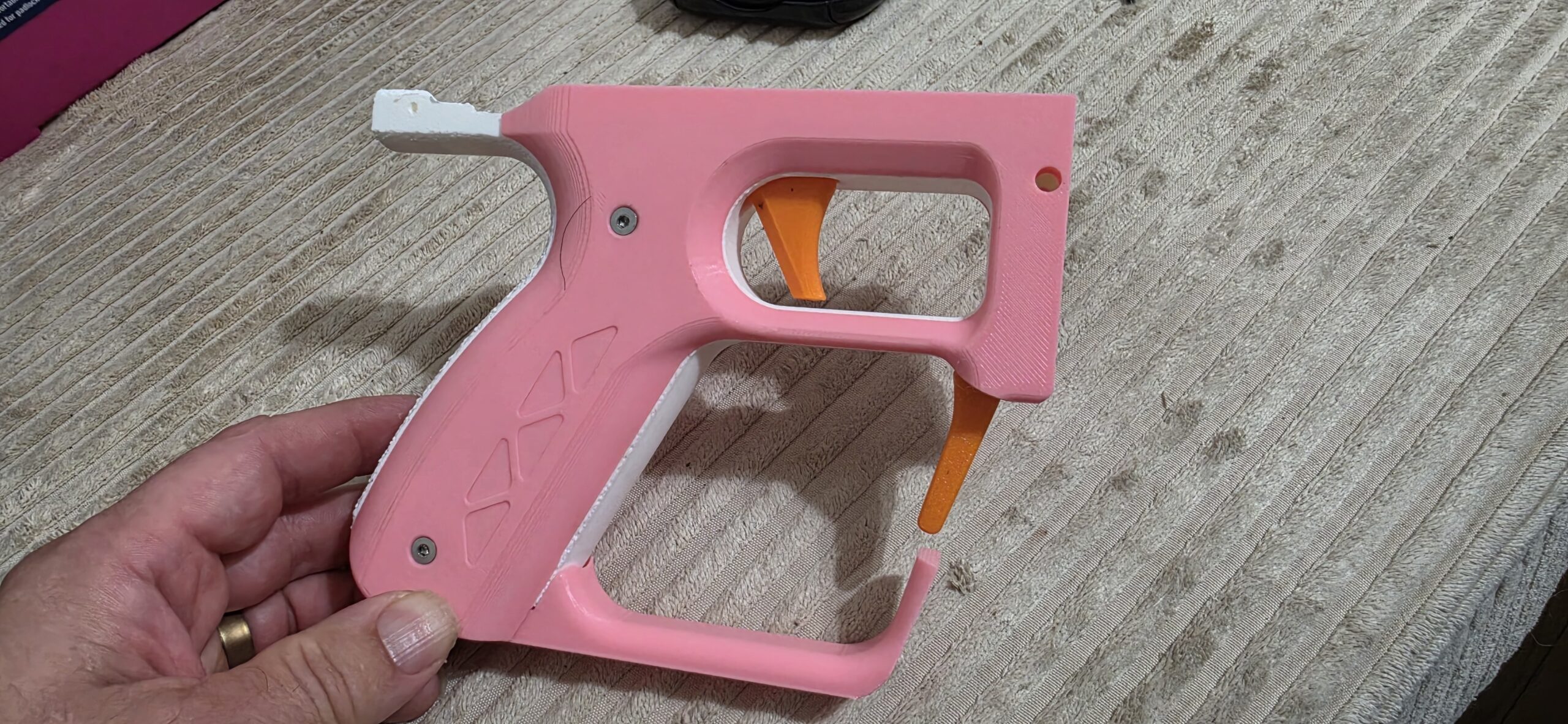 The magazine release lever goes at the front of the grip, whether you’re using standard Talons or Nightingale-style magazines. Line up one of your tiny springs between the lever and the grip (the indentations for the spring are impossible to miss), then drop in a dowel pin for retention.
The grip scales and base mate with each other, with tabs going into slots. Line up the base with the frame, sandwich the scales on either side, and insert your M3 screws where appropriate.
Part one is done!
Part 2: There’s a Catch!
Like the original Signet, the catch is contained within a housing (rear block) that doubles as the spring rest.
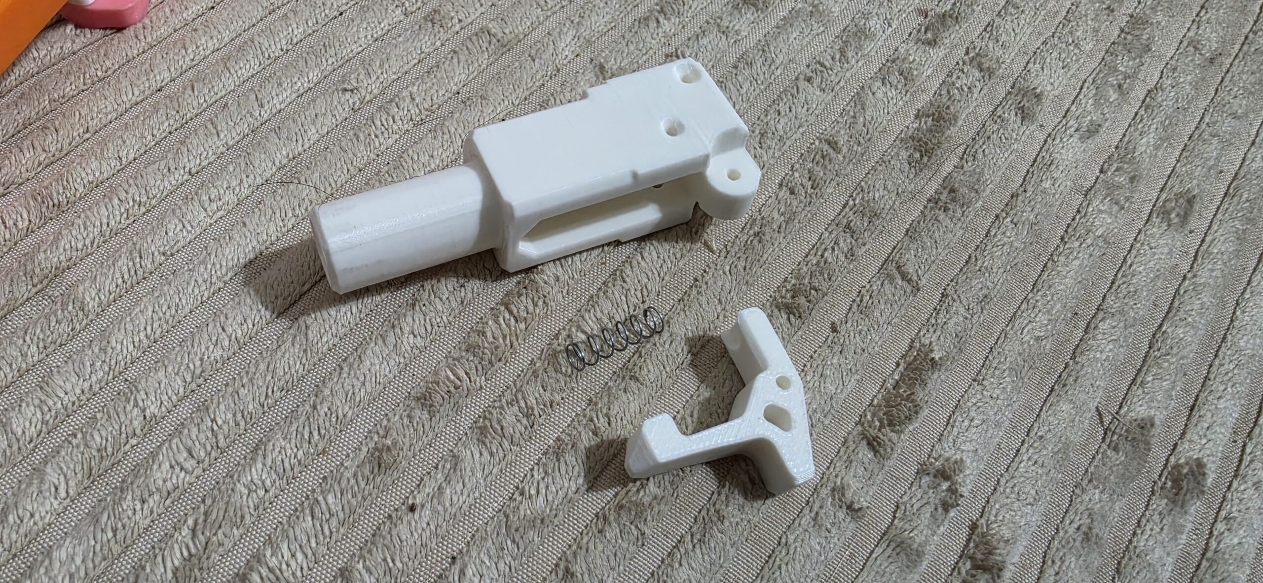
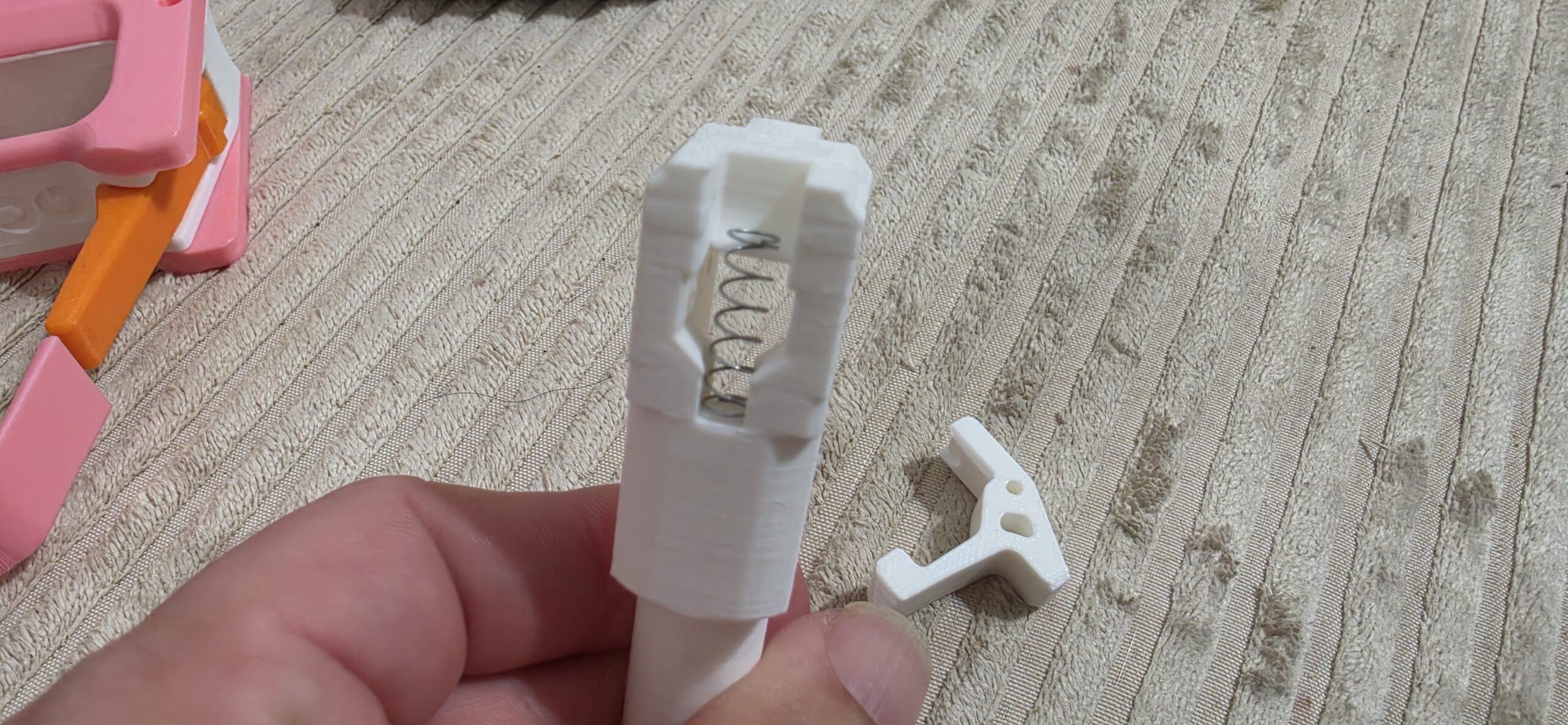
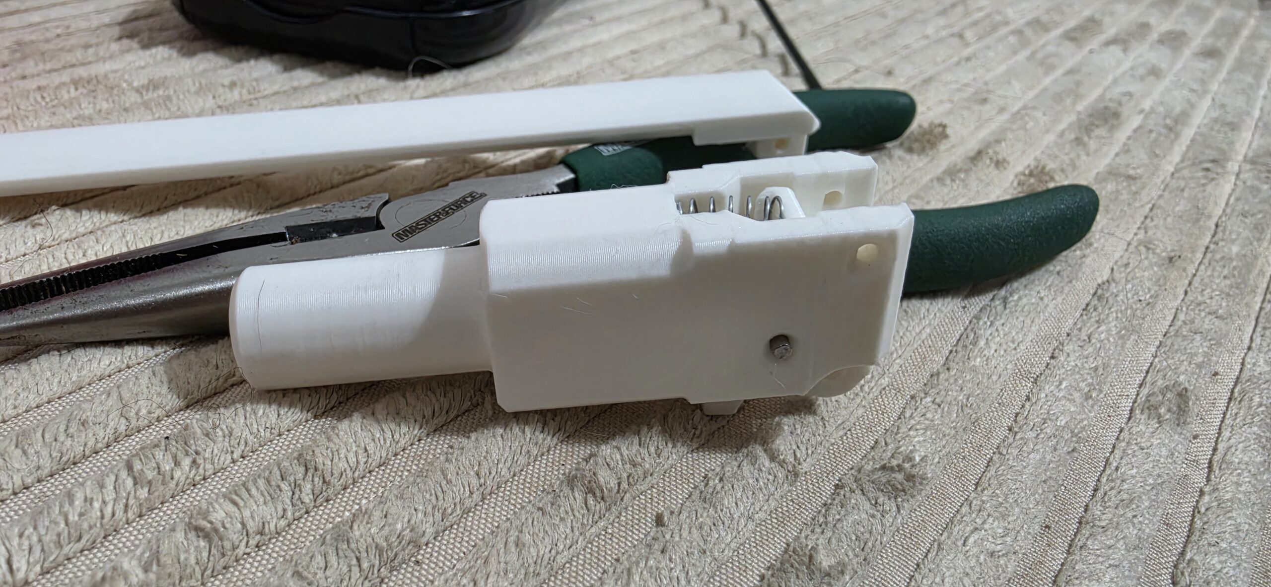
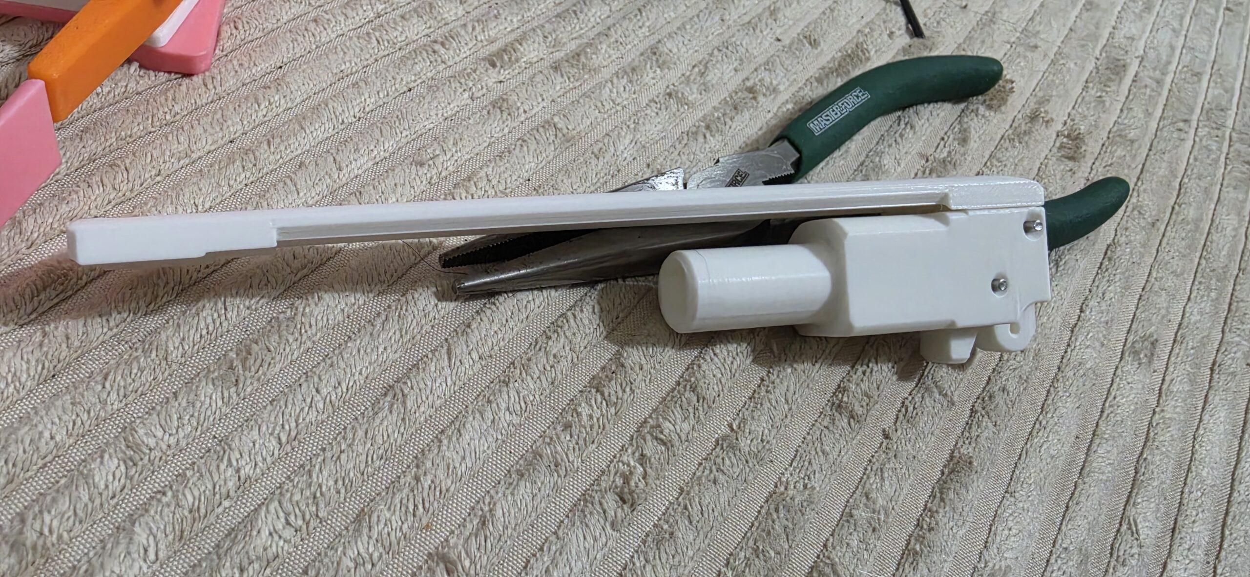
The location of the tiny spring here is slightly less obvious, but it slots into the middle of that rear block. You then slide the catch up into place, in the same orientation as the first picture in the gallery above. It takes a bit of fiddling with the spring, but you can line it all up, then insert a dowel pin to secure the catch.
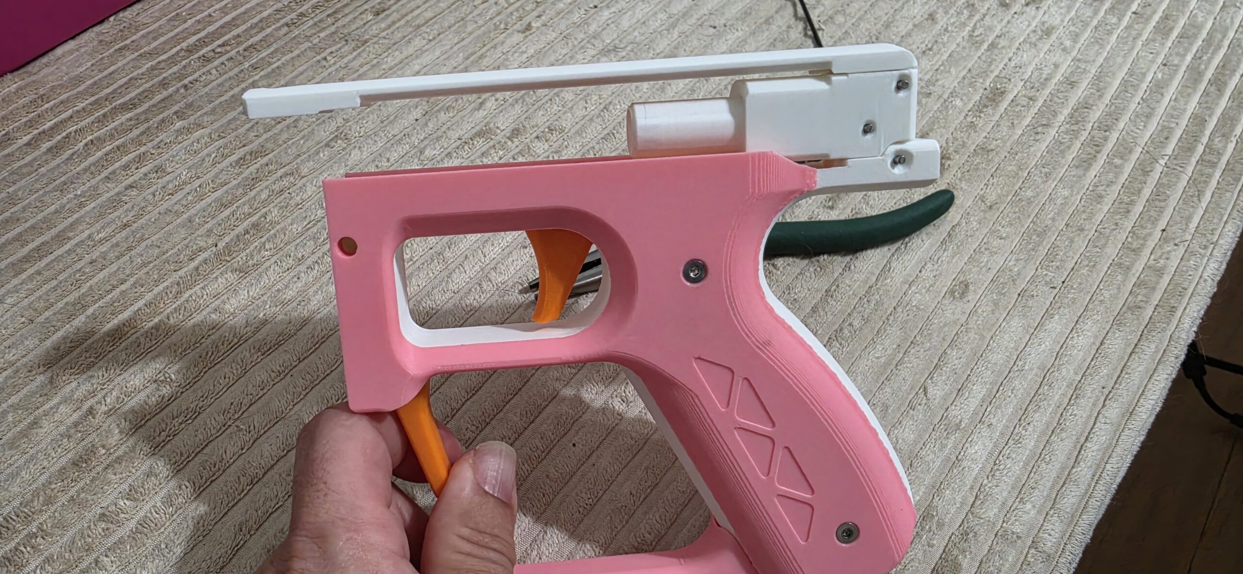 The frame top will mate with the rear block, using just a dowel pin, and will finish securing the spring so it doesn’t, well, spring out of place.
Grab yet another dowel pin, and put this assemblage of plastic pieces together with your grip!
You’re doing good so far. You should celebrate with a snack.
Part 3: Taking the Plunge
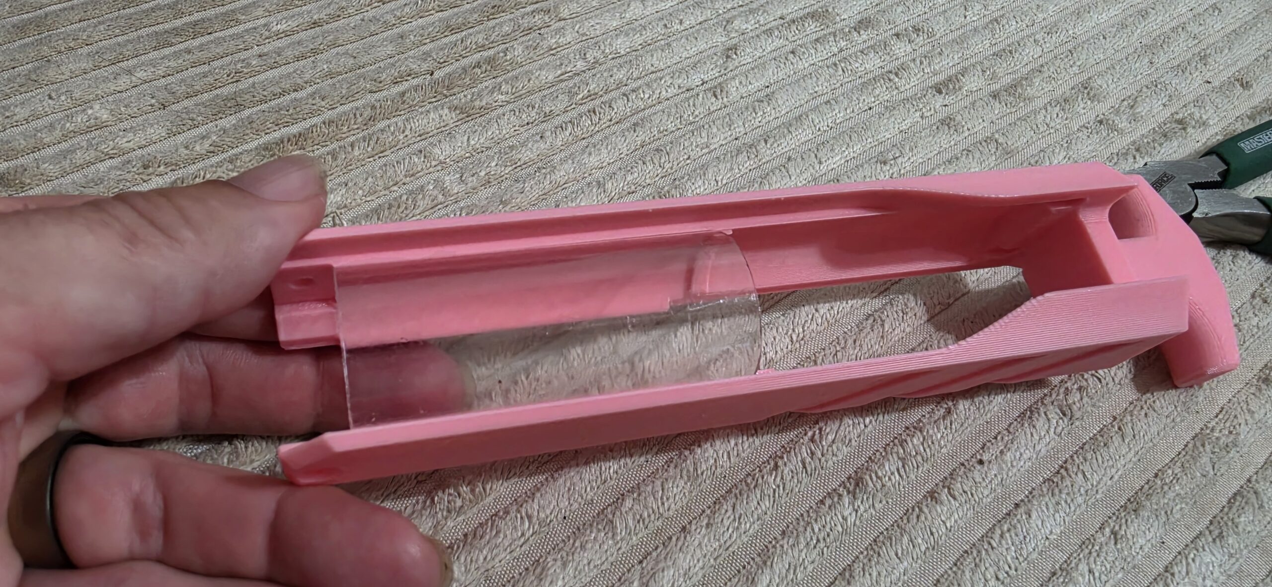
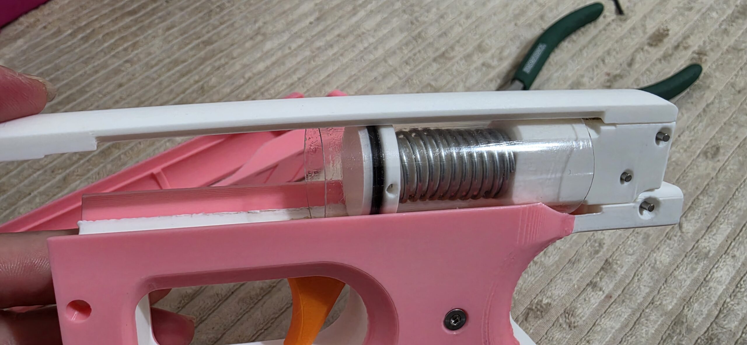
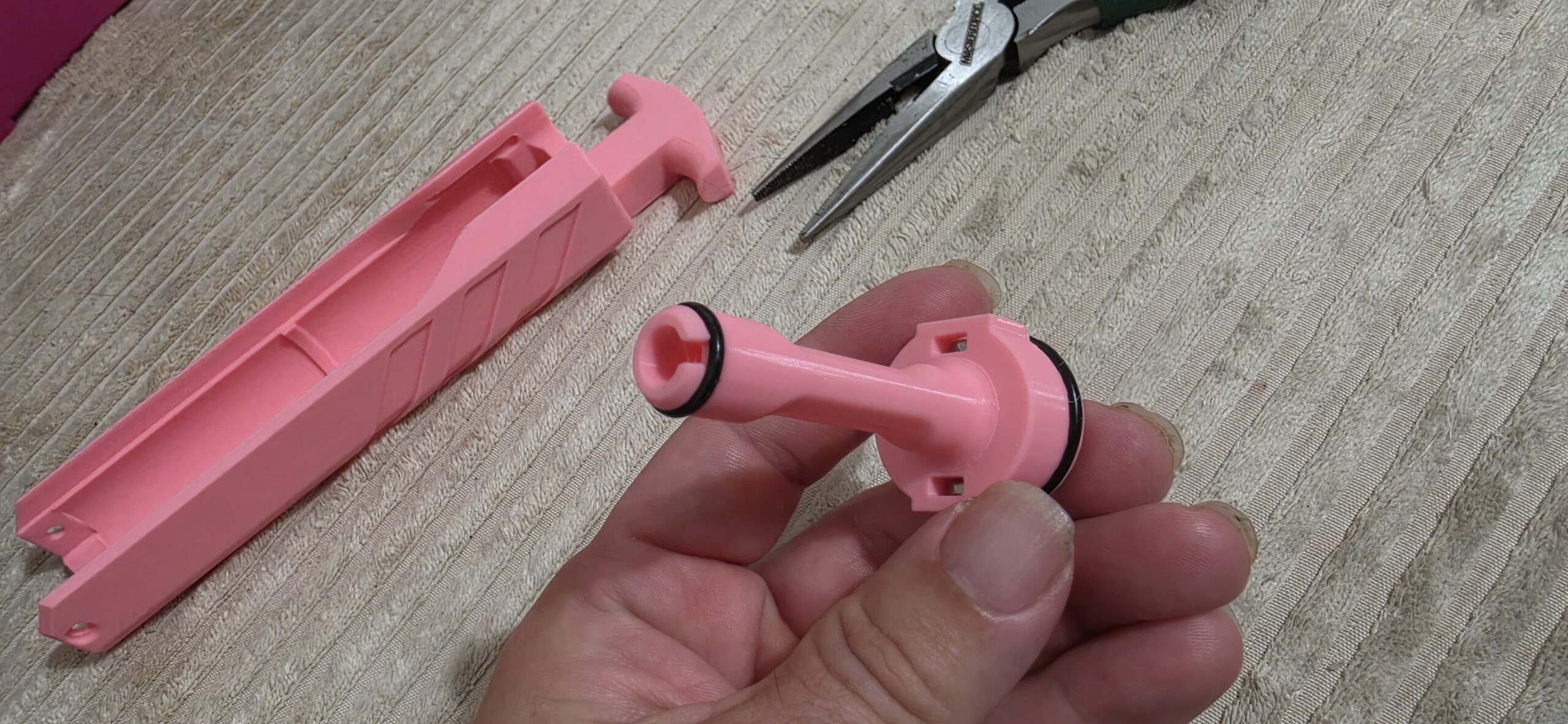
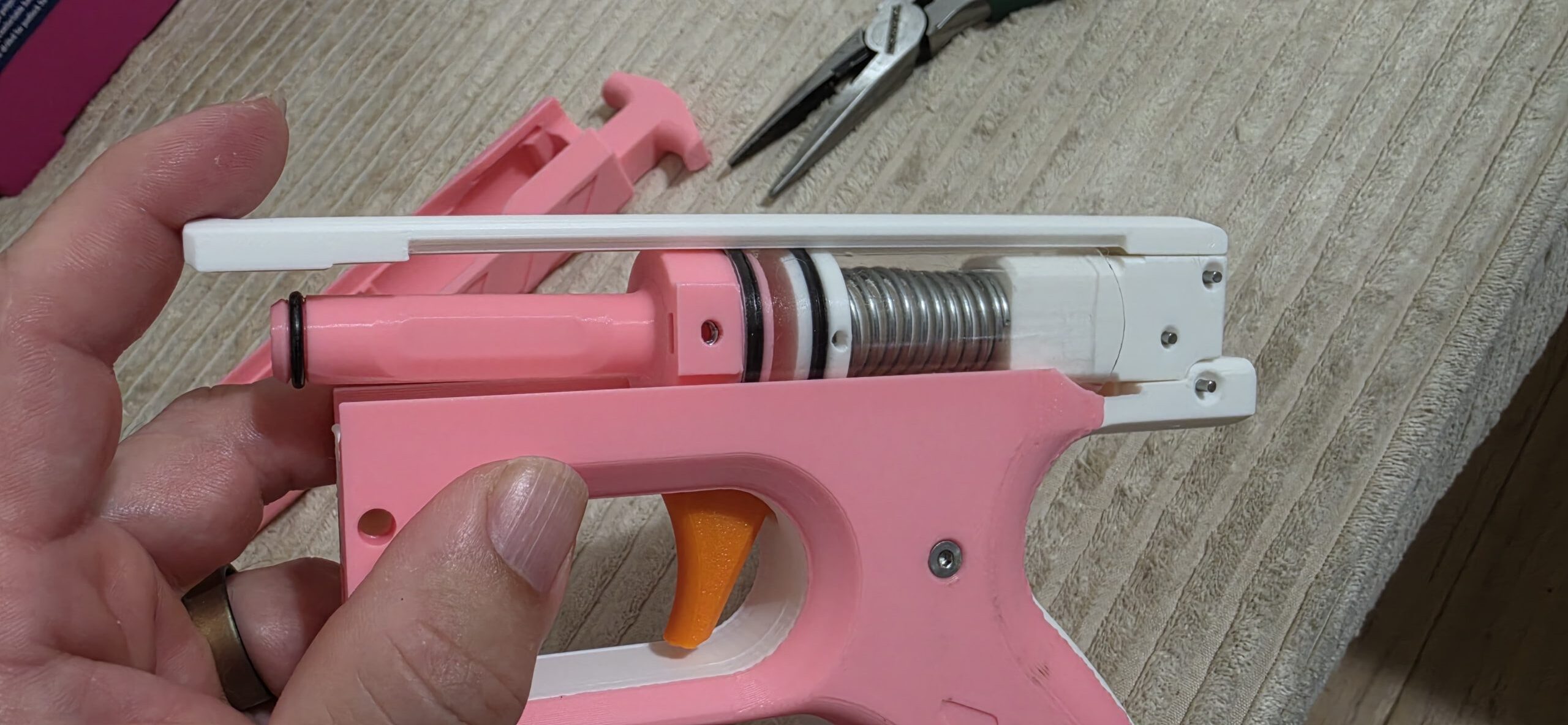
Double check that your plunger tube fits in its spot in your chosen priming slide. If it does, great! If it’s a bit too long, carefully trim it down until it fits. The tube should be 64mm long, but when you already have a template sitting there, why break out the measuring tape?
The plunger head is secured to the plunger rod by a dowel pin (who would have guessed?). Slide on one of the large o-rings, and grease it up. Then slide the plunger tube over it carefully, making sure the o-ring stays in place and isn’t stretched.
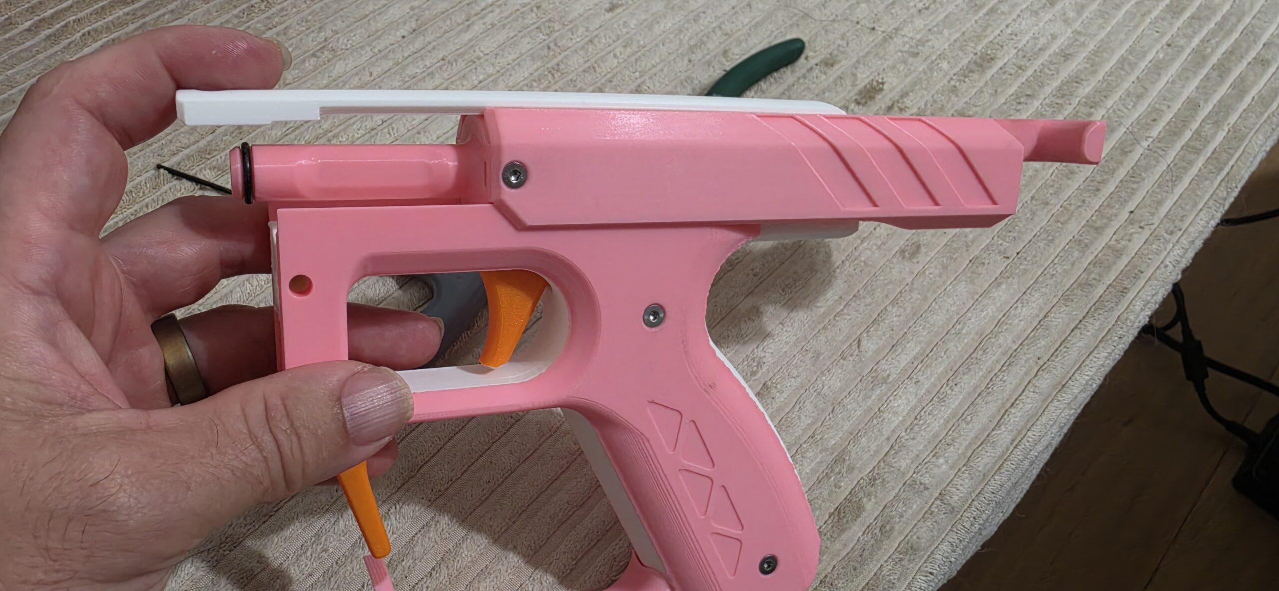 The ram has two slots for M3 nuts. Add the other large o-ring, along with the pusher o-ring. Insert the nuts carefully, then push the ram into the end of the plunger tube.
Add your power spring, then slide in all the plunger-associated bits. Make sure the plunger rod’s cutout is facing down! If you like, you can go ahead and push everything together to make sure the plunger actually catches. Don’t accidentally press the trigger and fire pieces across the room, though.
Finally, you’ll flex the priming slide over the plunger tube, and various grooves should snap into place. Use an M3 screw on either side to secure the slide to the pusher.
The back of the blaster is done! If you did this with the spring compressed, grab the slide and hold it while pressing the trigger so that you can slowly decompress.
Part 4: THE REST OF THE FREAKING BLASTER
Insert internet meme about drawing owls here.
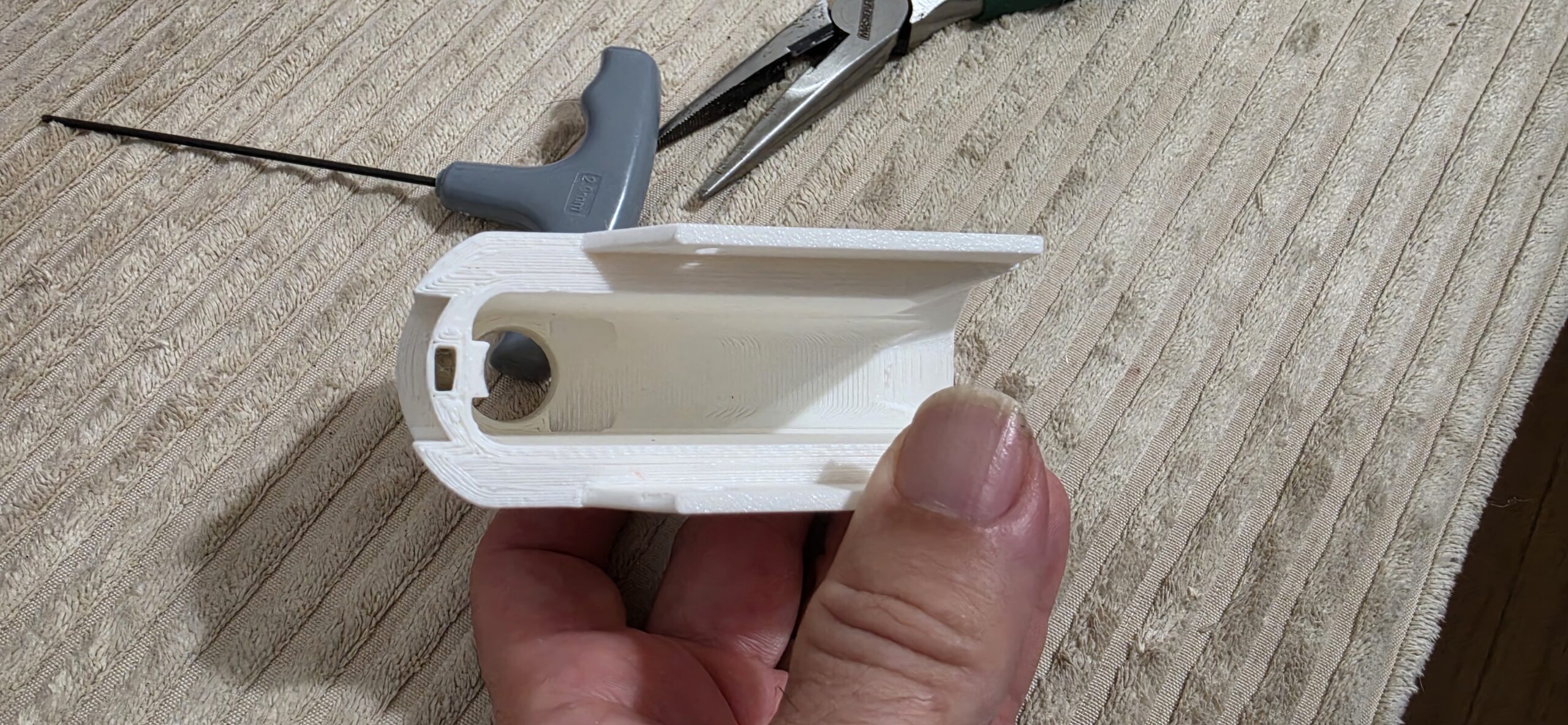
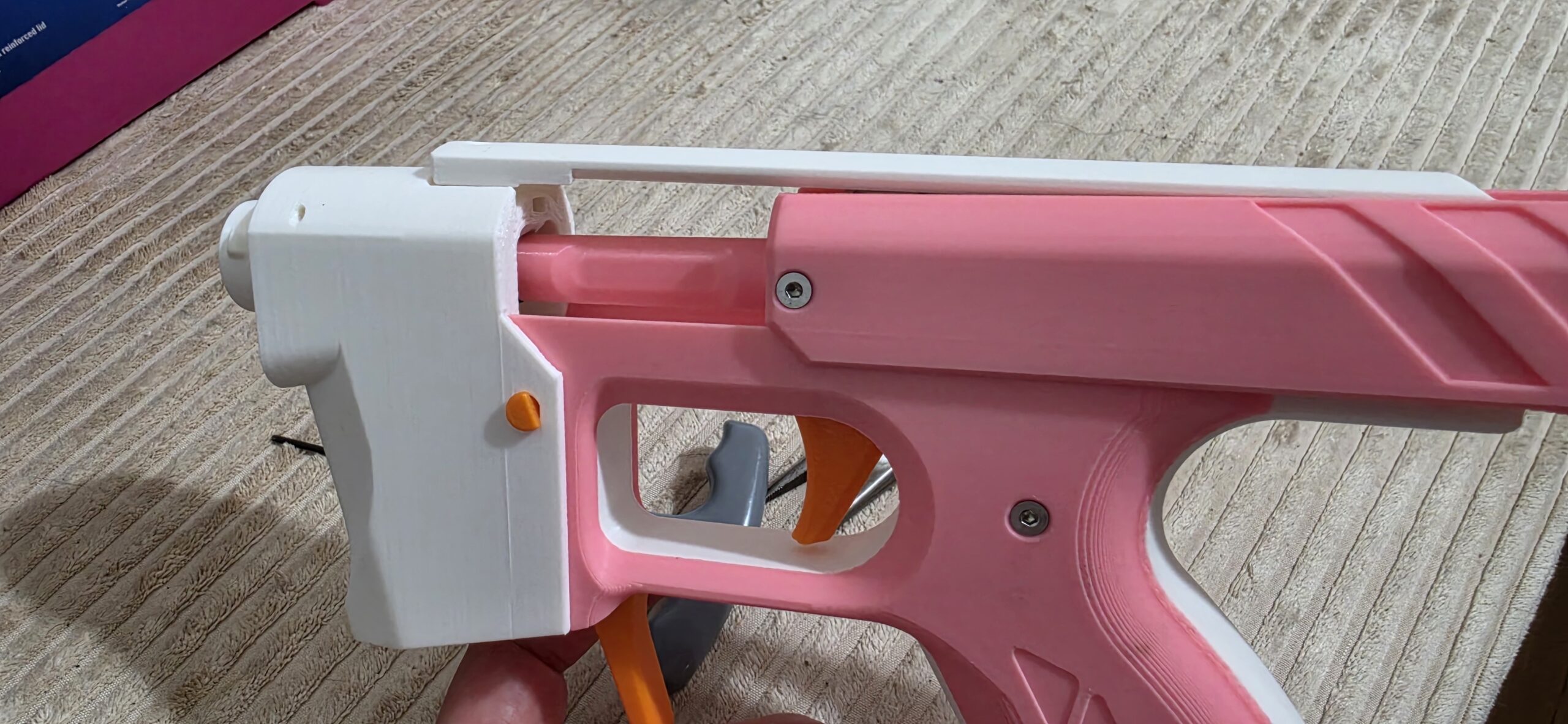
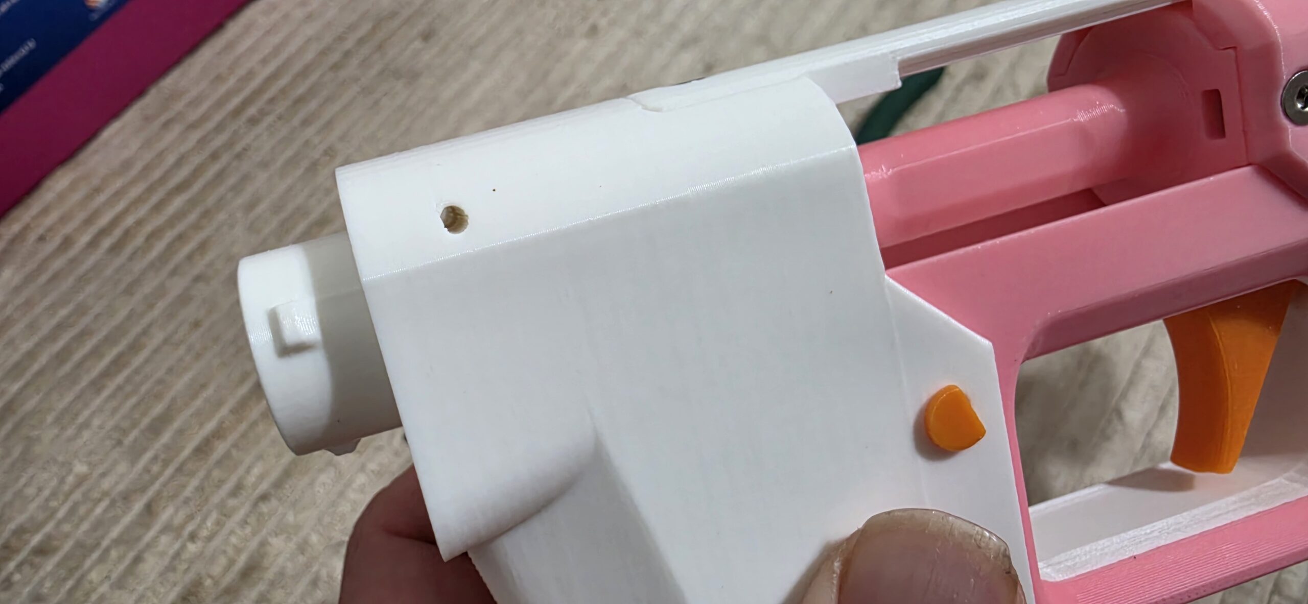
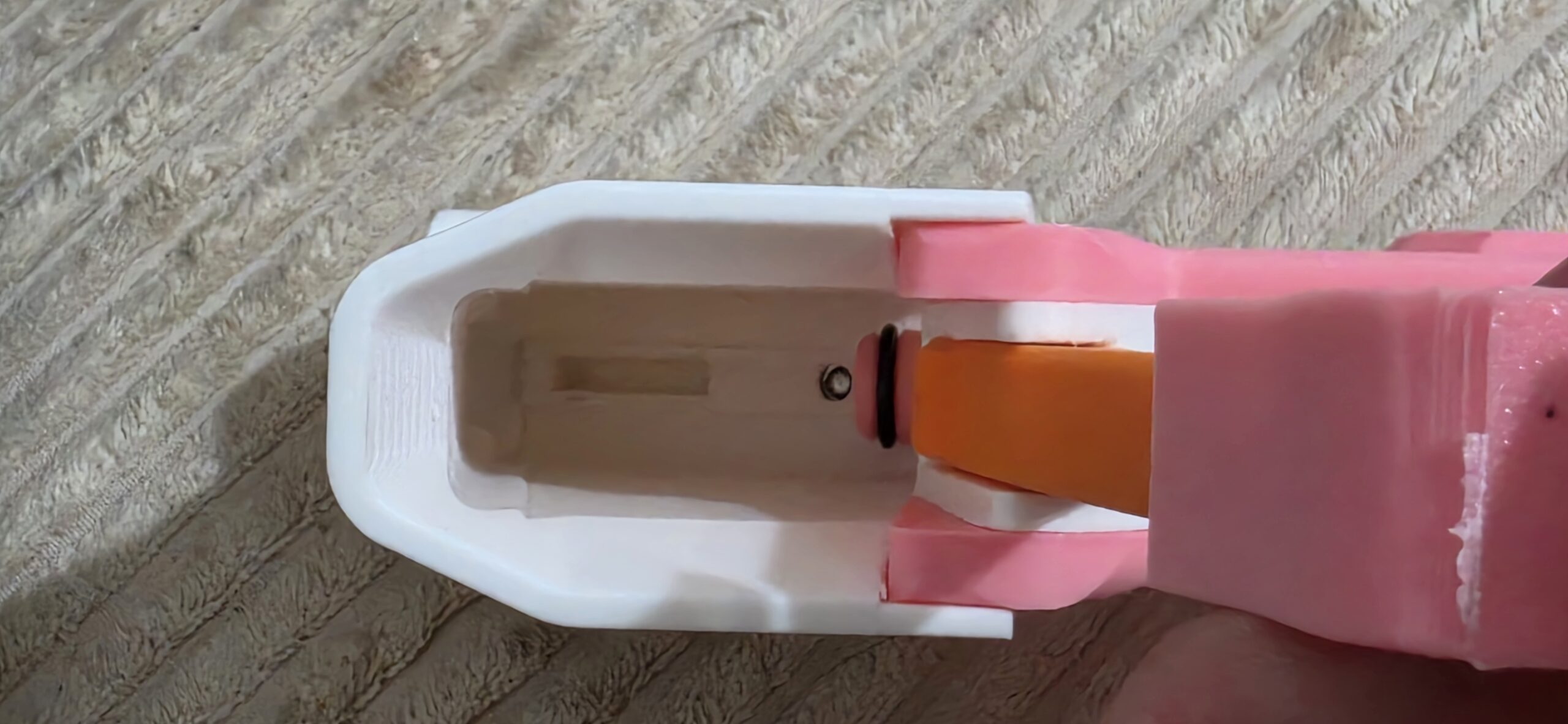
Check the magazine well that was printed, and make sure the slot at the top doesn’t have any supports inside. An M3 nut will slide in there. You can then push the magazine well onto the front of the blaster; an M3 screw will hold down the frame top to the magazine well, and a printed takedown pin can slide in from the side.
Note that there is another slot for a dowel pin, as well as a slot inside the magazine well. As of this writing, there’s nothing on the Printables page about it, but a printed part does exist. Whether it’s necessary is another matter, but that will be determined later (my blaster has operated great without such a piece present).
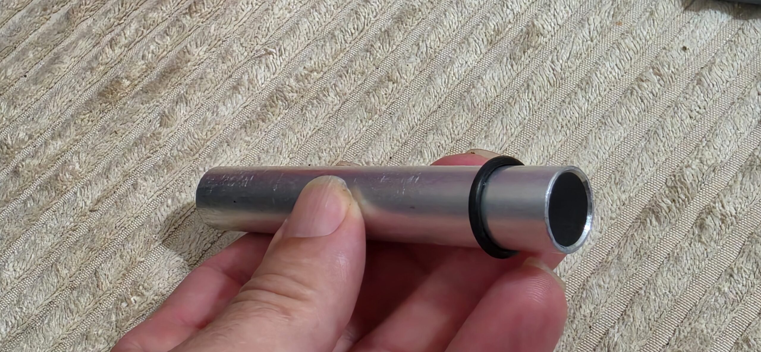
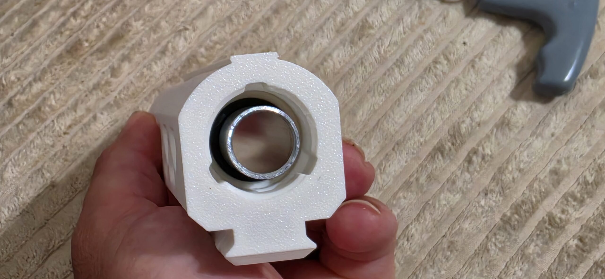
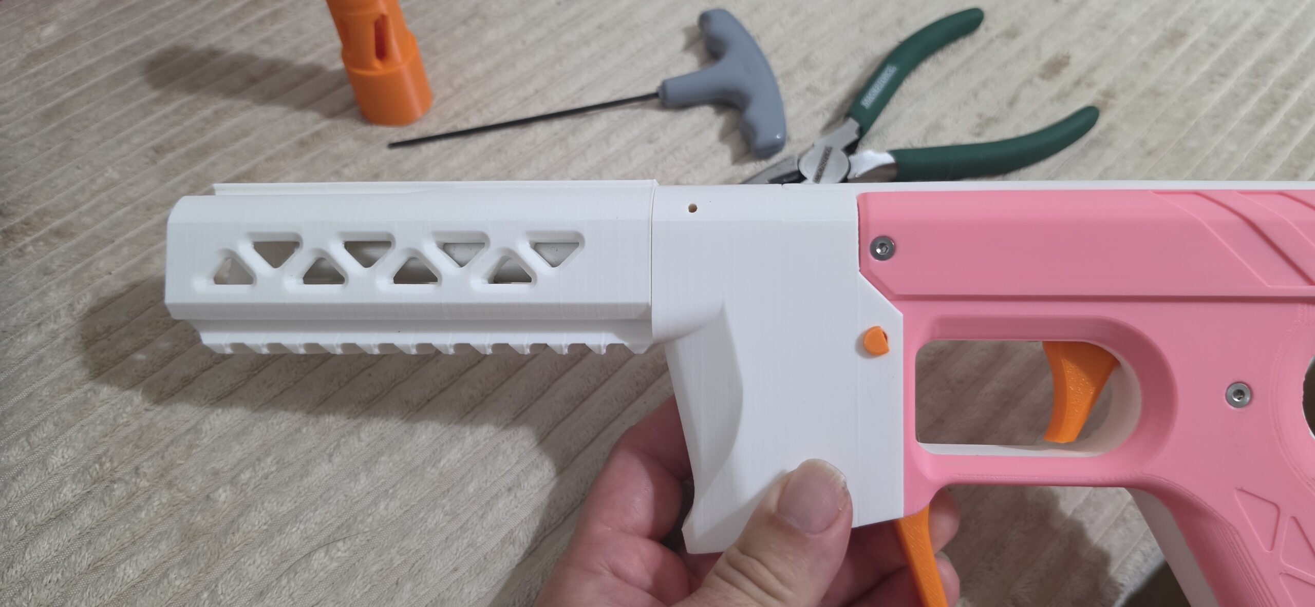
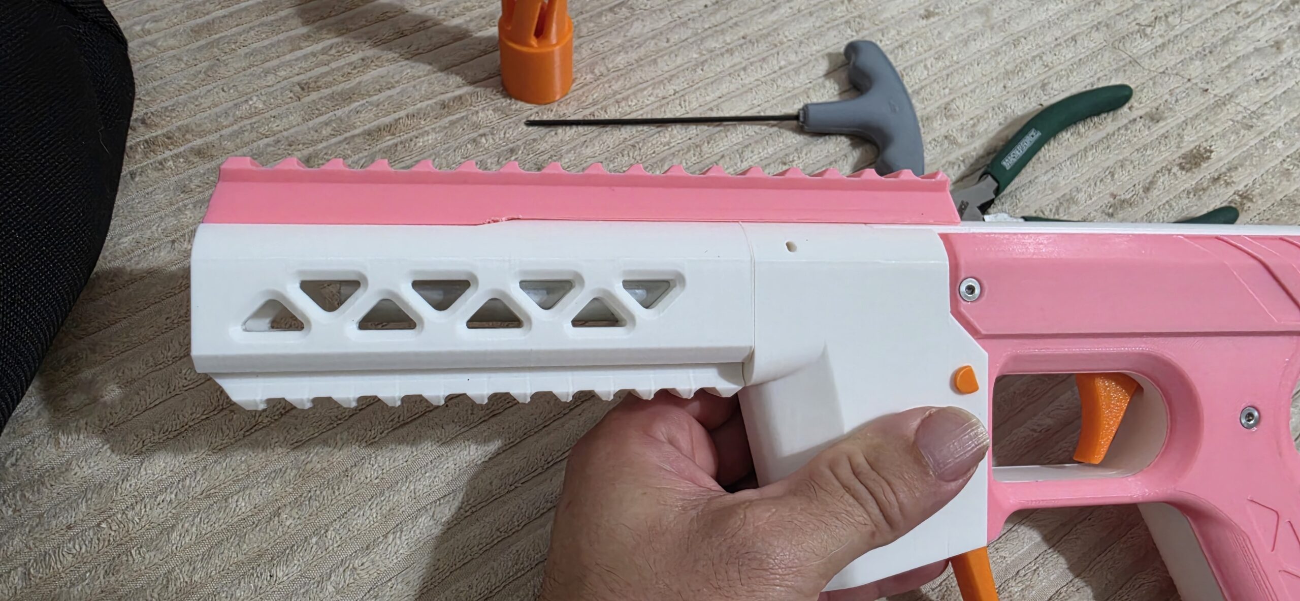
Put the collet o-ring over the barrel, and slide into the front of the blaster. The tactical muzzle will double as a collet of sorts, with a slot for the o-ring to squish into and secure the barrel. Slide the muzzle over the barrel and o-ring, twisting to lock in place like you would an NSstrike barrel attachment.
The tactical top rail can then be slid over the muzzle.
Last Bits!
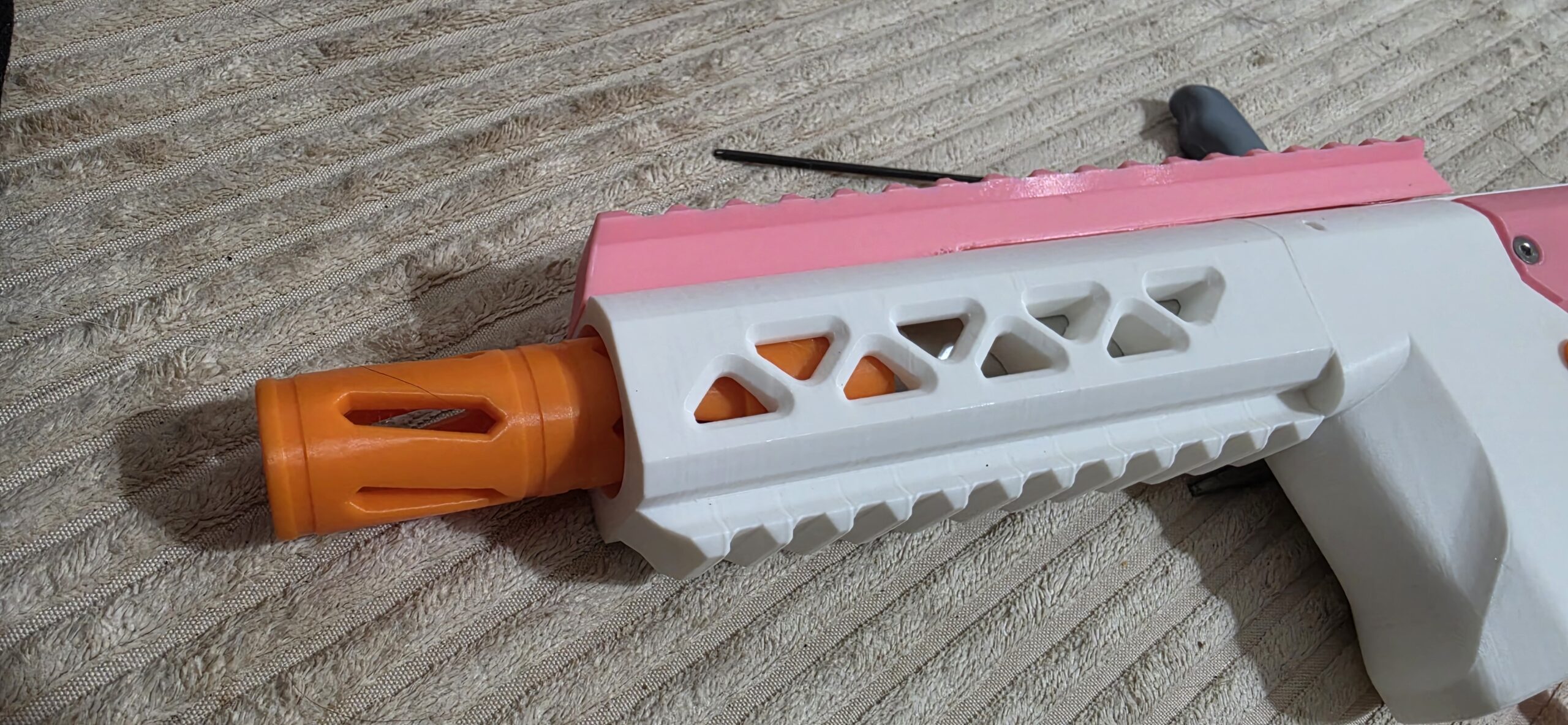 The blaster will work like this, but you should (of course) print a barrel tip. One muzzle break is included in the file set. However, I wanted to both have a PCAR and better secure the barrel from getting jostled out of place.
To that end, I remixed Chance’s Tangent PCAR to add a wide base that would tightly fit inside the tactical muzzle. It’s seen extended use, and only after a very long mission of HvZ did the barrel itself shift enough to cause any issues – at which point I just shoved back on the muzzle and fixed it.
The newest version of that remix should fit tighter still to prevent that happening again. We’ll see.